Scenario – Let us say I have a Customer who has a load balancing requirement, however, they do not utilise Overlay networking and, as a result, no Tier-0 or Tier-1 Gateways exist to form a software-defined routing architecture. As such, an Inline load balancer topology will not be possible. However, VLAN-backed NSX-T Segments are in place, as the customer currently utilises distributed firewalling.
This article looks at how we can deploy a Tier-1 Gateway for one-arm load balancing to backend virtual machines housed on VLAN-backed NSX-T Segments. Should we wish, we could expand the server pool by adding physical devices as well.
First of all, we will need to deploy a Tier-1 Gateway and, because we will be configuring a stateful service (load balancing), we need to house the Tier-1 Gateway on an edge cluster.
Important
You might think that, as we are only utilising Edges for load balancing traffic to a Server Pool of VMs housed on VLAN-backed Segments, they only need to be members of the VLAN Transport Zone. Not the case, as the Edges also need to be members of the Overlay Transport Zone. Why? Simple.
Edges use Bidirectional Forwarding Detection (BFD) for high-availability and failure detection between each other. As such, BFD utilises the Overlay (TEP) network, regardless of whether overlay networking is used or not. Edges in this scenario must be added to both VLAN AND Overlay Transport Zones. This is a crucial point to remember when configuring your Edges in the design.
Edge Configuration
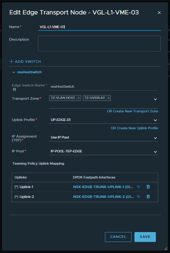
1. Deploy your Edges and ensure that they participate in the same VLAN Transport Zone as the ESXi Hosts AND the Overlay Transport Zone. As discussed earlier, the Overlay Transport Zone is required for Edge HA and BFD connectivity, regardless of whether overlay networking is being utilised.
2. Create an Edge Cluster and add the previously created Edge VMs.

Network Configuration
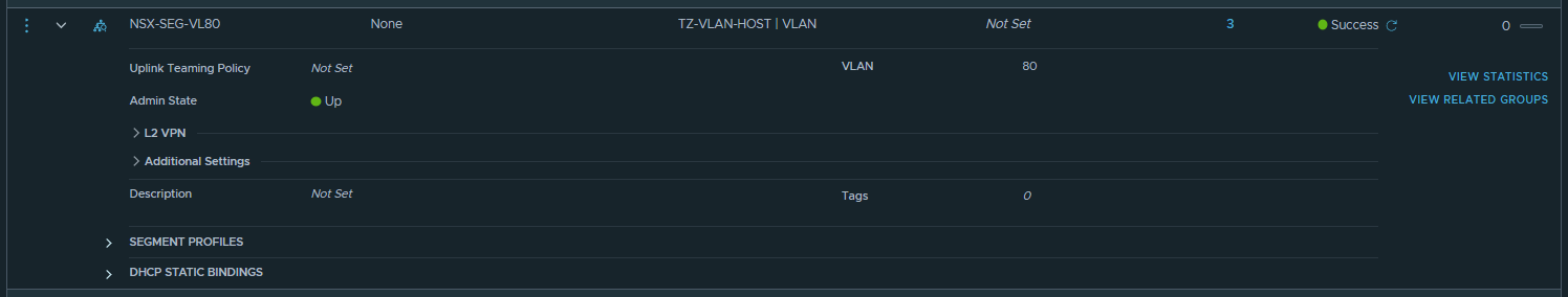
1. Create a VLAN-backed NSX-T Segment. This will house a) our backend server pool members and b) the Service Interface of our Tier-1 Gateway, which we’ll configure in a later step.
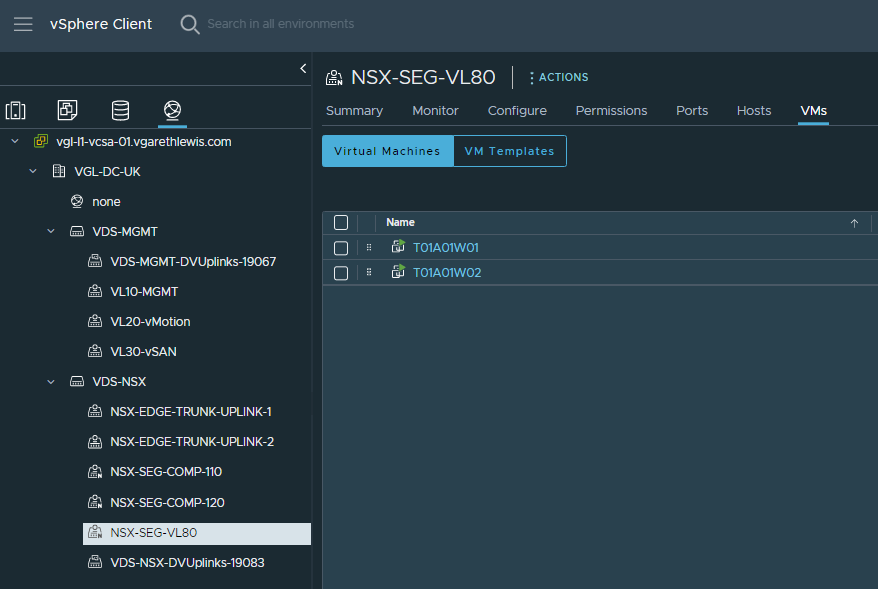
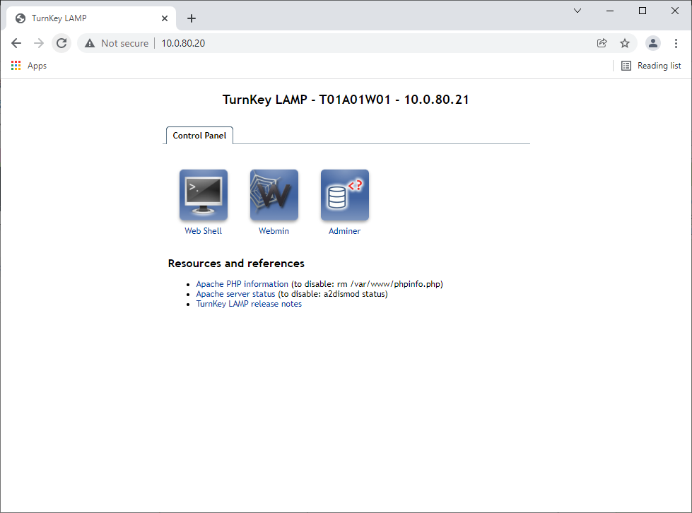
2. Place the backend server virtual machines onto the VLAN-backed NSX-T Segment. In our case, T01A01W01 and T01A01W02.
Tier-1 Gateway Configuration
1. Create a Tier-1 Gateway and place it on the newly created Edge Cluster.
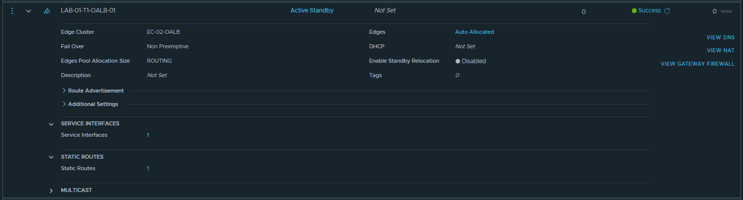
2. Create a Service Interface on the Tier-1 Gateway, give it an IP address, and connect it to the previously created VLAN-backed NSX-T Segment. The Service Interface will provide the Tier-1 Gateway with a leg into the same L2 broadcast domain as our backend VMs.

3. Create a static route targeting the ToR switches as a next hop, and allocate the Service Interface as the Scope.

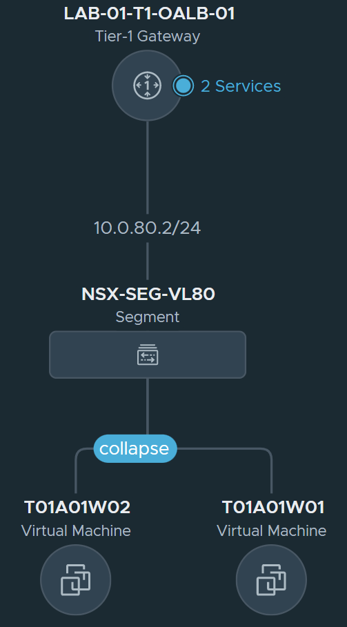
4. At this point, we have created the below topology. Next, we’ll create and configure our one-arm Load Balancer.
Load Balancer Configuration
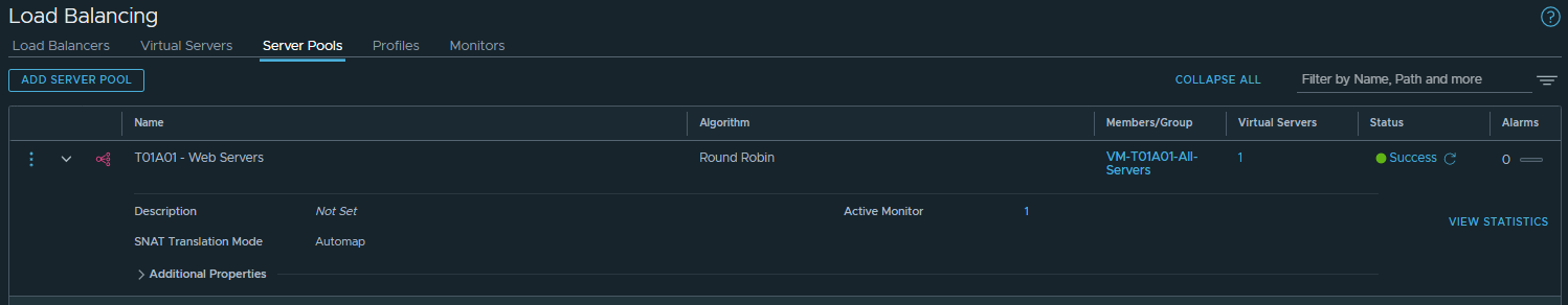
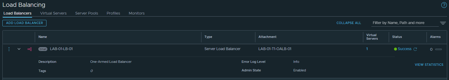
1. In the below screenshots, I create a Load Balancer and place it on our Tier-1 Gateway. The VMs previously mentioned (T01A01W01 and T01A01W02) are added to a Server Pool and, for One-Arm load-balancing, we must ensure SNAT Translation Mode is set to Automap.
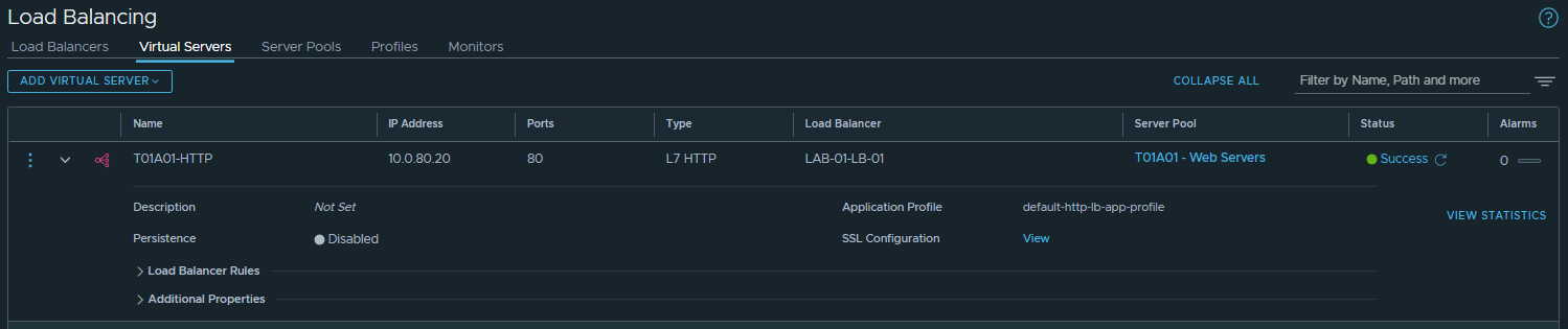
2. Finally, testing access to the Virtual Server IP validates connectivity to both Server Pool members via Round Robin.

In Summary
In this article, we deployed a Tier-1 Gateway solely for one-arm load balancing to backend virtual machines housed on VLAN-backed NSX-T Segments. We could, should there be a requirement, have added physical devices to the server pool as well.
Most importantly, we added our Edges to the same VLAN Transport Zone as our ESXi hosts AND the Overlay Transport Zone. The latter is required for Edge HA BFD connectivity, regardless of whether overlay networking is used.
Leave a Reply