Scenario – Let us say I have a Customer who has a load balancing requirement, however, they do not utilise Overlay networking and, as a result, no Tier-0 or Tier-1 Gateways exist to form a software-defined routing architecture. As such, an Inline load balancer topology will not be possible. However, VLAN-backed NSX-T Segments are in place, as the customer currently utilises distributed firewalling.
This article looks at how we can deploy a Tier-1 Gateway for one-arm load balancing to backend virtual machines housed on VLAN-backed NSX-T Segments. Should we wish, we could expand the server pool by adding physical devices as well.
In this second post we take a look at the alternative load balancer mode – In-Line/Transparent mode. First of all, unlike the One-Armed/Proxy mode, In-Line load balancers require two logical interfaces (LIFs); one Uplink LIF (connected to either a DLR or upstream Edge) and one Internal LIF. The Internal LIF is directly connected to the network segment housing the back-end servers requiring load-balancing. In addition to this (and unlike the One-Armed/Proxy load balancer), In-Line load balancers are required to act as the default gateway for all back-end servers.
Welcome to the first in a series of posts covering VMware NSX Edge load balancers. These posts will dive into the two main flavours – ‘One-Armed’ and ‘In Line’. We will cover use-cases for each option.
NSX Edge load balancers allow us to distribute incoming requests across a number of servers (aka – members) in order to achieve optimal resource utilisation, maximise throughput, minimise response time, and avoid application overload. NSX Edges allow load balancing up to Layer 7.
One-Armed/Proxy Mode
In this first post, we deploy an NSX Edge, enable the load balancer feature, and configure it in One-Armed mode (aka – Proxy, SNAT, non-transparent mode). This One-Armed/Proxy mode is the simplest of the two deployments, and utilises a single internal Logical Interface (LIF) (i.e. – it’s ‘one arm’).
This flavour of NSX Edge load balancer utilises its own IP address as the source address to send requests to back-end/member servers. The member servers see this traffic as originating from the load balancer and not the client and, as a result, all responses are sent directly to the load balancer. So, nice and simple, and this is usually my go-to solution where I have a requirement to load balance across a number of member servers for resilience.
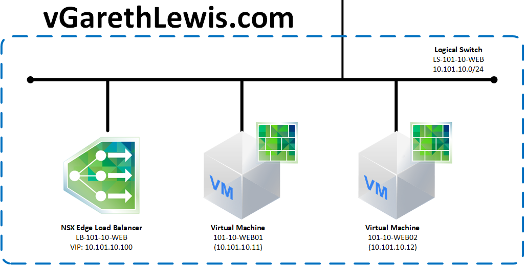
Topology
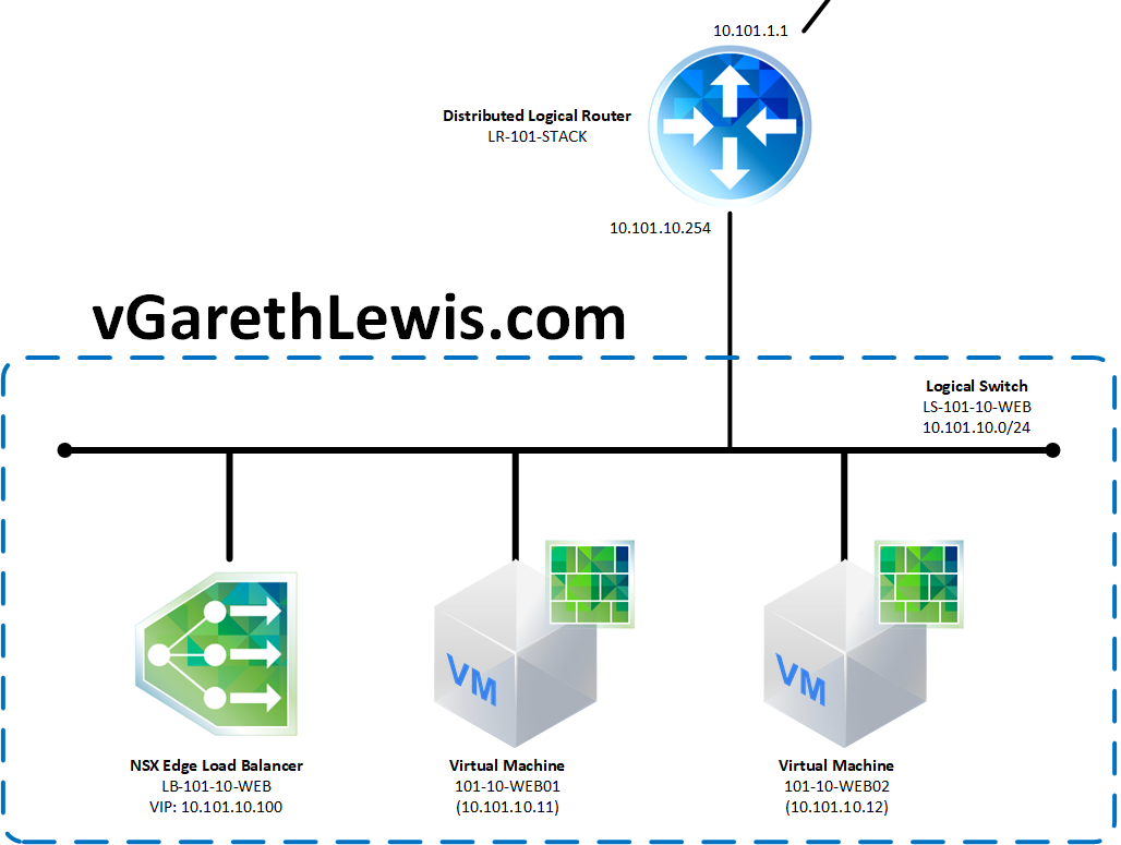
In this article we have a basic topology consisting of a NSX Edge load balancer (LB-101-10-WEB / 10.101.10.100) and two back-end/Member servers (101-10-WEB01 / 10.101.10.11 and 101-10-WEB02 / 10.101.10.12), all of which are housed on the same Logical Switch (10.101.10.0/24).
NSX Edge Load Balancers: Part 1 – One-Armed/Proxy Mode
Note, this article assumes your Logical Switches are already in play, traffic is able to route directly to each of the back-end servers, and you have created the necessary NSX Distributed Firewall rules. In this example, I will be configuring the NSX Edge load balancer to pass HTTP traffic to the back-end/Member servers.
NSX Edge – Deployment
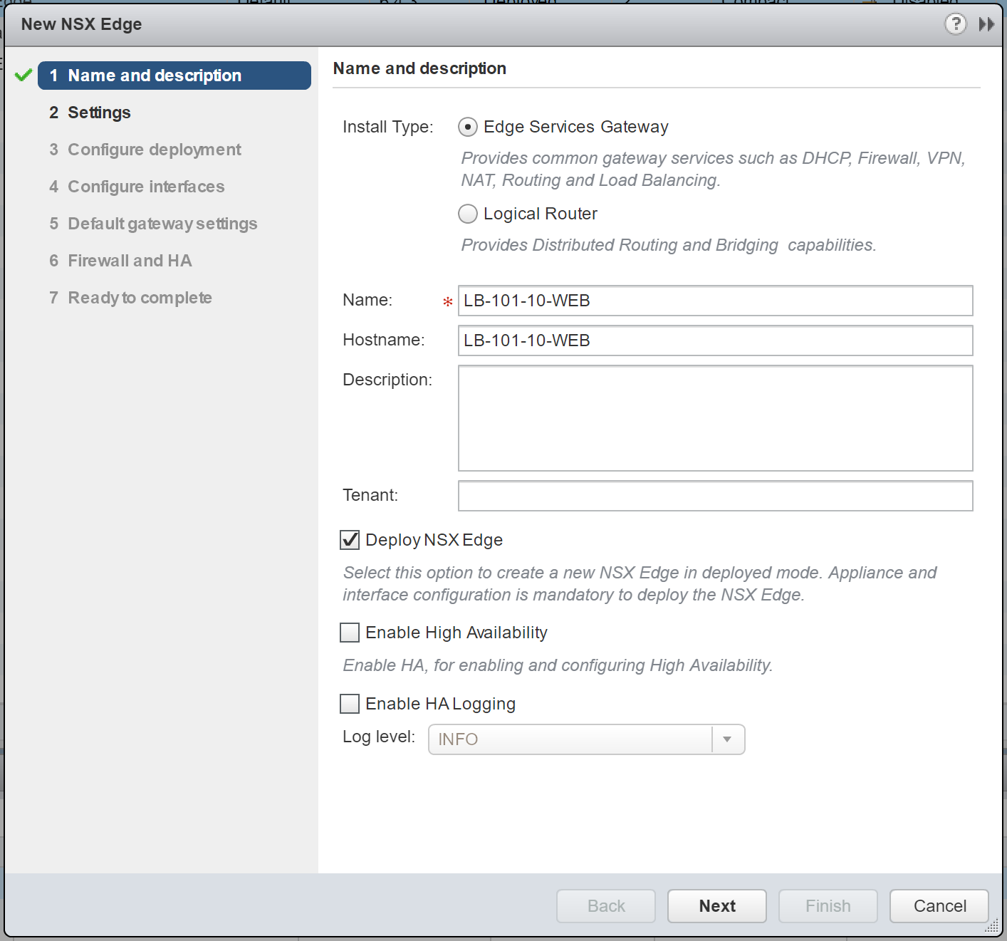
1. Create a new NSX Edge Services Gateway. Note, for my lab environment I will not enable High Availability. When ready, click Next.
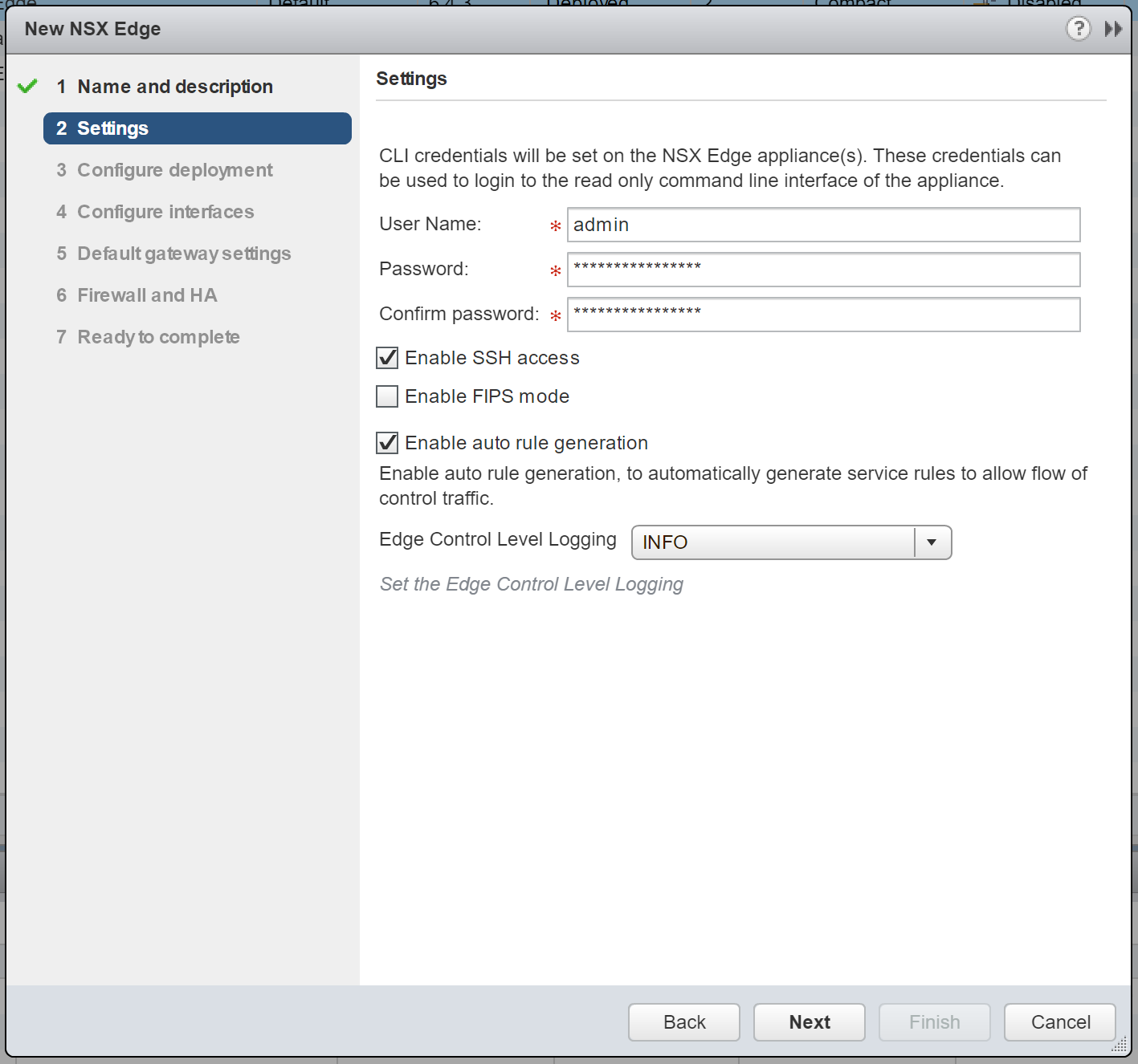
2.Configure the CLI credentials and click Next.
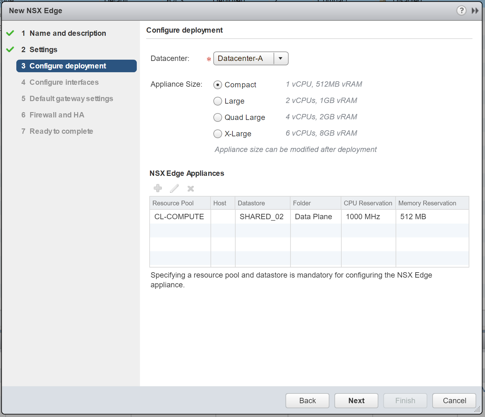
3. Configure the appliance size and resources. Again, for lab purposes, the Compact appliance size is appropriate. When ready, click Next.
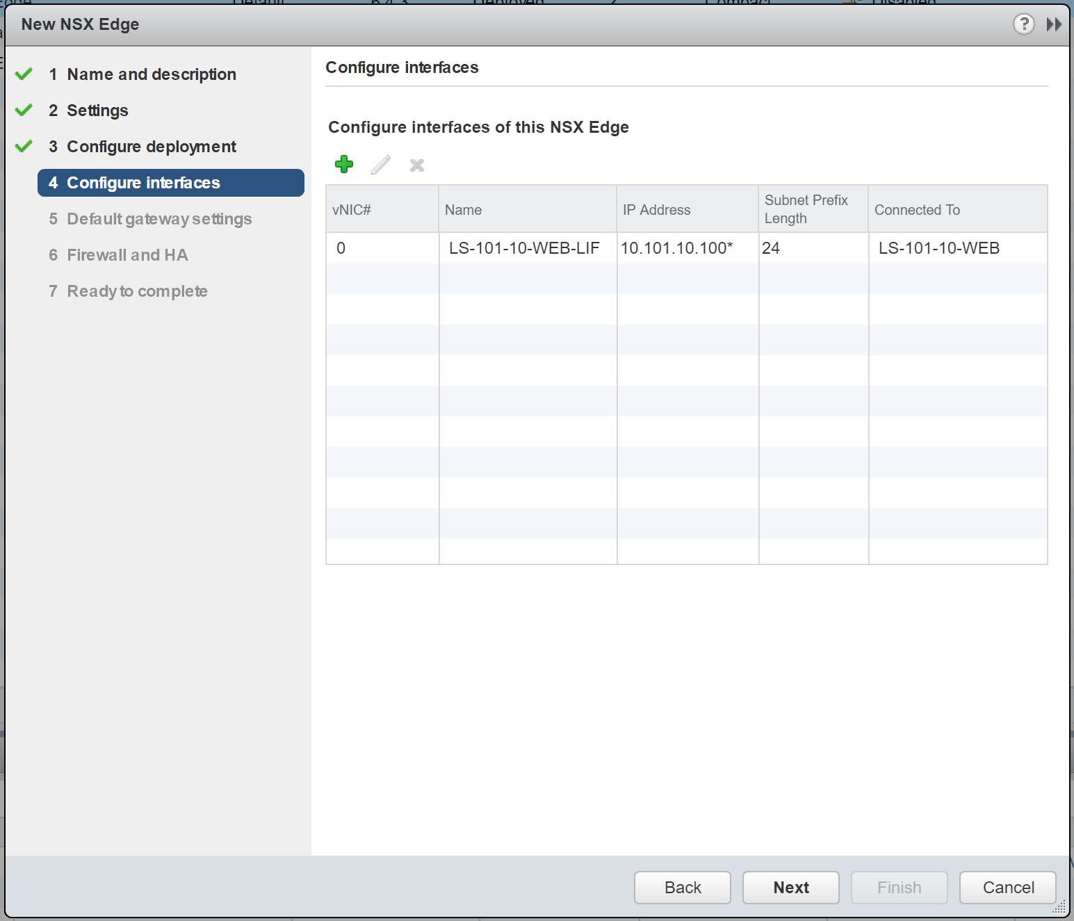
4. Next up, we need to configure a single (one-armed) interface. Click the + button to begin.
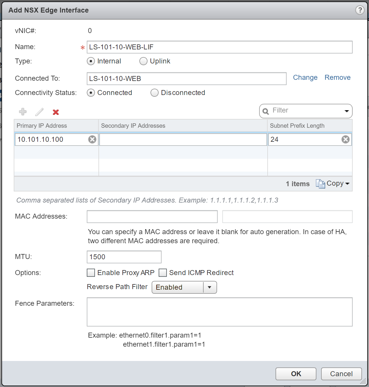
5. Give the interface a name, select Internal, and connect it to the same Logical Switch which houses both back-end web servers. Assign a primary IP address (this will be used as the load balancer’s virtual IP address) and, when ready, click OK.
Note – 10.101.10.100 has been assigned to the internal LIF and will be utilised in a future step as the virtual IP address of our new application pool. Additional/secondary IP addresses can be added and assigned to additional application pools (more on this on a later step), meaning one load balancer is capable of load balancing multiple applications.
6. Confirm the configuration and click Next.
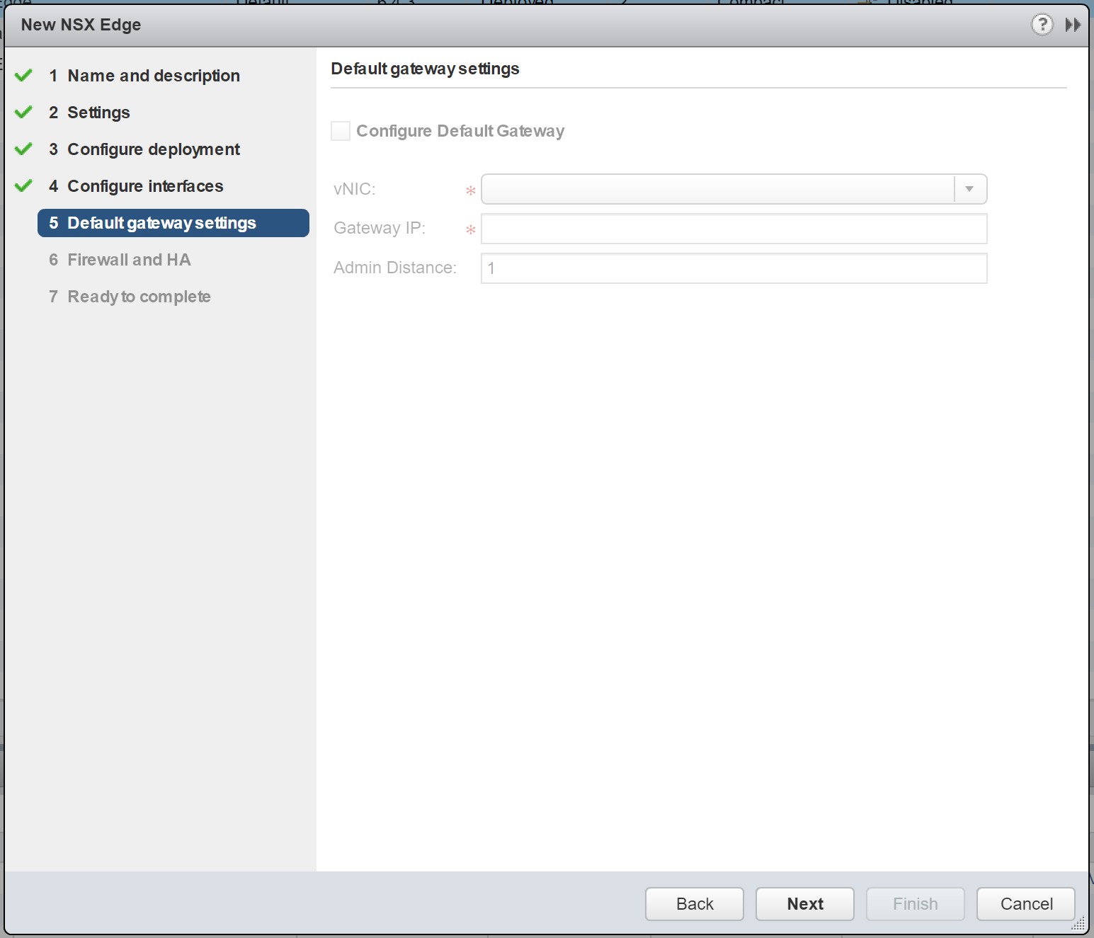
7. As the NSX Edge will not have an Uplink LIF, we will not be able to configure a default gateway. Click Next.
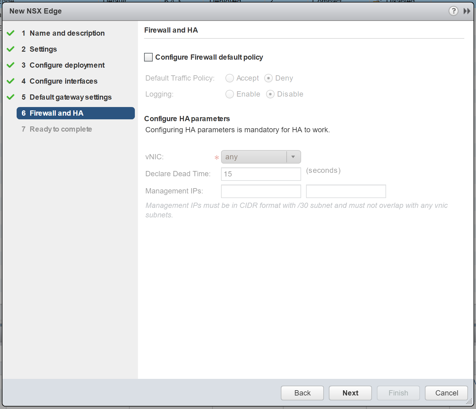
8. For lab purposes, I will not configure any firewall policies. Also, as we are not deploying the appliance in HA mode, all HA parameters will be greyed-out. Click Next.
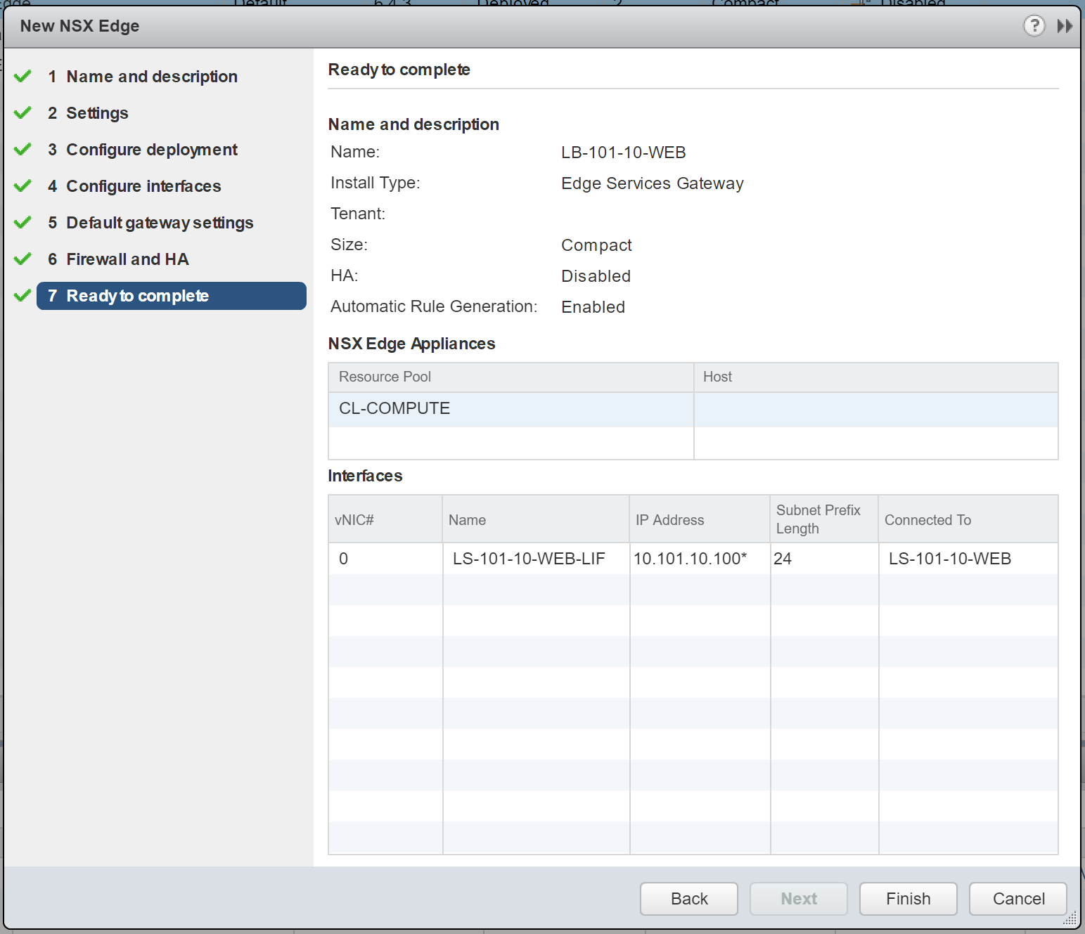
9. Confirm the NSX Edge configuration, and click Finish to deploy.
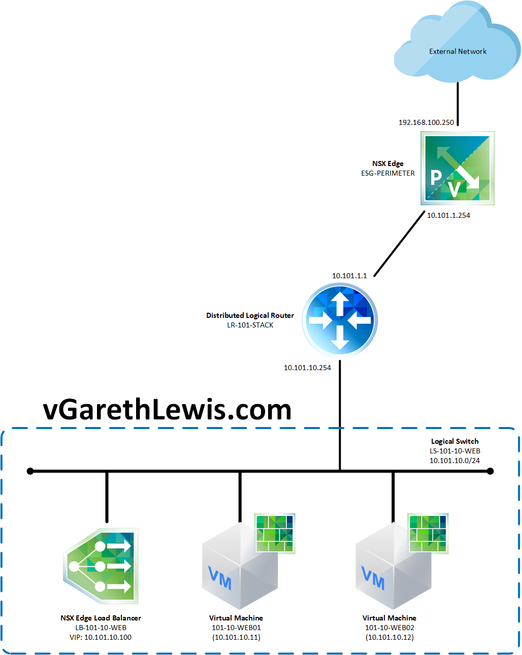
NSX Edge – Routing
Here in Lab World, I don’t have OSPF/BGP configured, so we’ll create a static route to enable traffic to flow upstream. Looking at the topology a little more closely, you’ll note the NSX Edge load balancer has a next hop of 10.101.10.254 (the internal LIF of the DLR ).
Configure a VMware NSX Edge Static Route
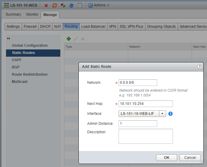
To configure the static route, simply jump into the configuration console of the newly created NSX Edge, browse to Manage > Routing > Static Routes, and click +. Configure accordingly and click OK.
NSX Edge – One-Armed Load Balancer Configuration
Now that our new NSX Edge has been deployed, we will enable the load balancer feature and configure in One-Armed/Proxy Mode.
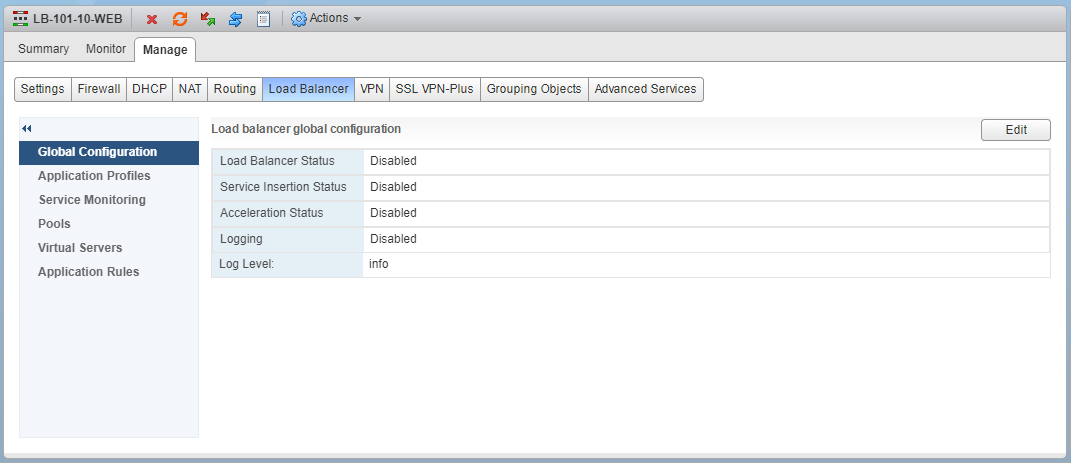
1. Browse to Manage > Load Balancer > Global Configuration and click Edit.
2. Ensure Enable Load Balancer is ticked, and click OK.
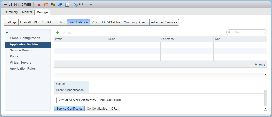
3. Browse to Manager > Load Balancer > Application Profiles and click +.
Application Profiles – An Application Profile is used to define the behaviour of a particular type of network traffic, and is associated with a virtual server (virtual IP address). The virtual server then processes traffic according to the values specified in the Application Profile. This allows us to perform traffic management tasks with greater ease and efficiency.
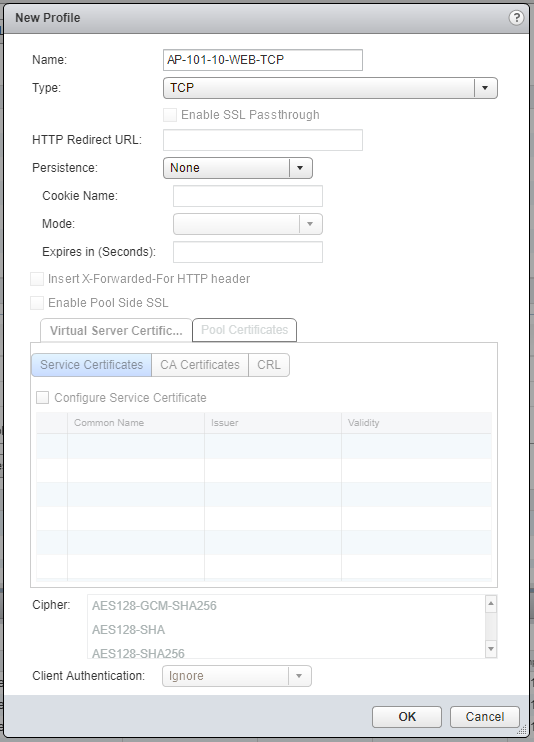
4. As mentioned at the start of this post, we are only interested in load balancing for resilience. As such (and as detailed below), we will set the Application Profile Type to TCP.
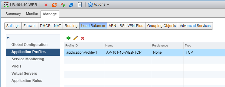
5. Confirm creation of the new Application Profile.
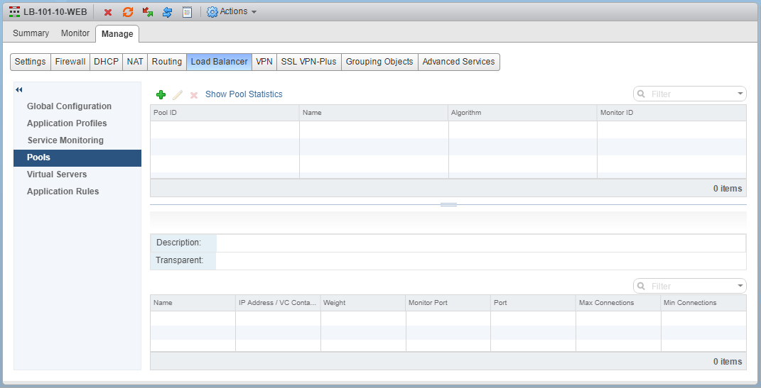
6. Browse to Manager > Load Balancer > Pools and click +.
Pools – A Pool is simply a group of back-end servers (aka, Members), and is configured with a load-balancing distribution method/algorithm. A service monitor (optional) can also be configured and, as this suggests, is used to perform health checks on its Members.
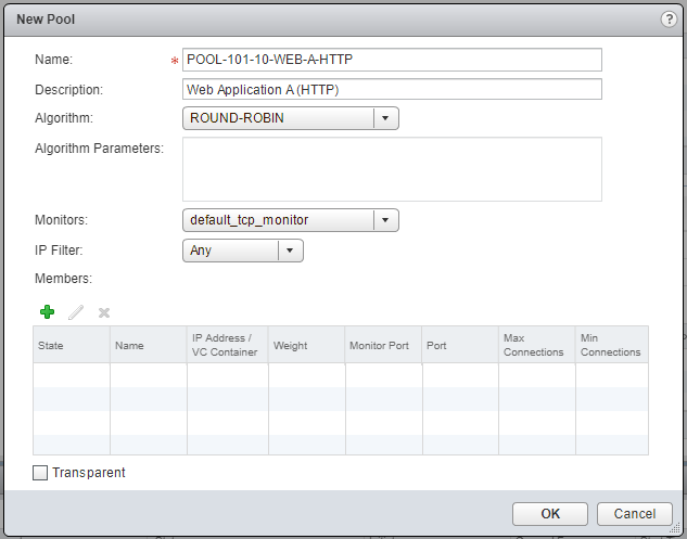
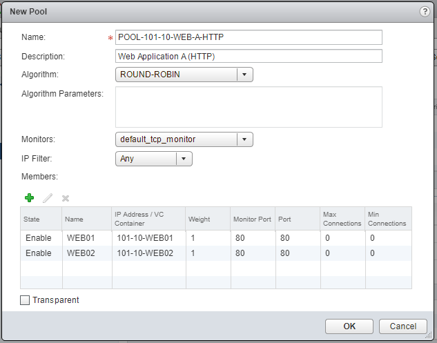
7. Give your new Pool a Name, Description, choose its distribution method/Algorithm, and Monitors.
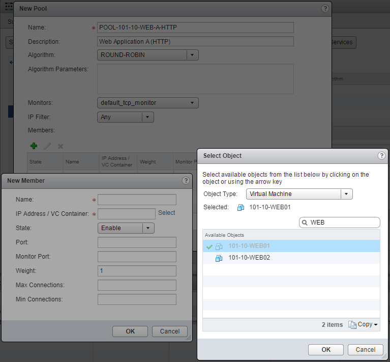
8. When ready, click + to add your back-end/member servers. For this either click Select to choose a vSphere Object, or simply type the destination’s IP address.
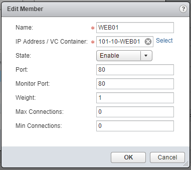
9. Define the Port (in this instance I am load-balancing HTTP/80 traffic), as well as the Monitor Port (here I use port 80 again). When done, click OK.
10. Confirm your configuration by clicking OK.
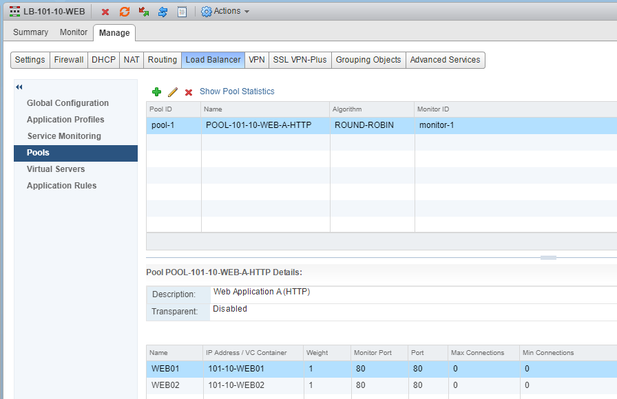
11. Confirm creation of the new Pool.
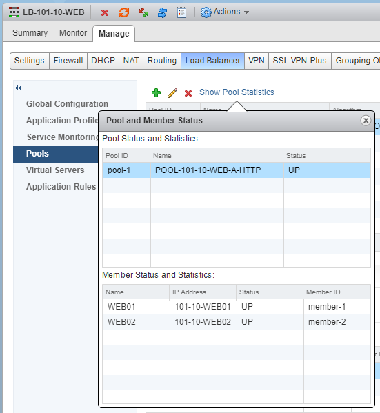
12. Check your newly created Pool’s health status by clicking Show Pool Statistics. The Status of both the Pool and it’s Members should show UP.
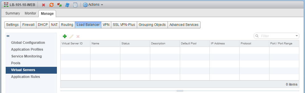
13. Browse to Virtual Servers and click +.
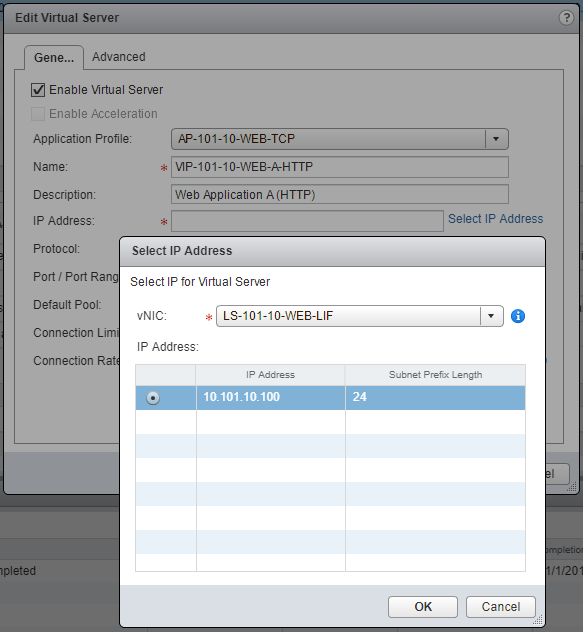
14. From the Application Profile drop-down menu, select the recently created Application Profile, give the Virtual Server a Name and Description, and click Select IP Address to select the IP address which we allocated to the internal LIF when we created the load balancer.
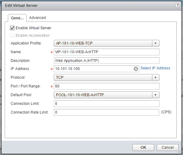
15. Lastly, set the Protocol to TCP, Port/Port Range to 80, and set the the Default Pool to the pool we created in step 6.
16. Confirm creation of the new Virtual Server.
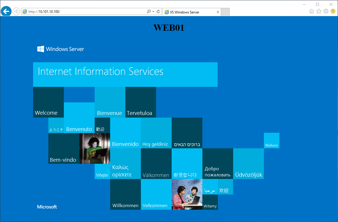
17. Finally, browse to the Virtual Server IP address to confirm load-balancing to each of the Pool Members is successful. In the below screenshot, traffic is routed to the VM, 101-10-WEB01.
18. After Refreshing the browser, I am directed to 101-10-WEB02.
Conclusion
In the next post we’ll cover the second flavour of NSX Edge load balancer, In-Line mode (aka, Transparent mode) and, in future posts, we’ll look at use cases for both, as well as troubleshooting tips.
We use cookies to ensure that we give you the best experience on our website. If you continue to use this site we will assume that you are happy with it.