In Part 1 we looked at the deployment of the NSX Edge load balancer in One-Armed/Proxy mode. As detailed, this flavour of NSX Edge load balancer requires nothing from its back-end server pool members, and enables us to quickly and easily add a load balancer to an existing network segment which houses a number of proposed back-end servers.
In-Line/Transparent Mode
In this second post we take a look at the alternative load balancer mode – In-Line/Transparent mode. First of all, unlike the One-Armed/Proxy mode, In-Line load balancers require two logical interfaces (LIFs); one Uplink LIF (connected to either a DLR or upstream Edge) and one Internal LIF. The Internal LIF is directly connected to the network segment housing the back-end servers requiring load-balancing. In addition to this (and unlike the One-Armed/Proxy load balancer), In-Line load balancers are required to act as the default gateway for all back-end servers.
Secondly, a NSX Edge in Transparent mode will only perform DNAT on user traffic, with client IP addresses visible to all the back-end servers. As the NSX Edge will be acting as the default gateway for all back-end servers, it will be on the path of the server response.
Topology
In this post, I utilise the below topology. The NSX Edge load balancer (LB-101) has two LIFs; an Uplink LIF (10.101.1.1) which will act as the VIP (Virtual Server), and an Internal LIF (10.101.10.254) which is directly connected to the Logical Switch, LS-101-10-WEB (10.101.10.0/24). Both back-end servers (101-10-WEB01 and 101-10-WEB02) have been configured to utilise the load balancer’s Internal LIF as their default gateway.

Note, this article assumes your Logical Switches are already in place, and you have created the necessary NSX Distributed Firewall rules. In this example, I will configure the NSX Edge load balancer to pass HTTP Traffic to the back-end Member servers.
NSX Edge – Deployment
1. Create a new NSX Edge Services Gateway. Note, for my lab environment I will not enable High Availability. When ready, click Next.

2. Configure CLI credentials, and click Next.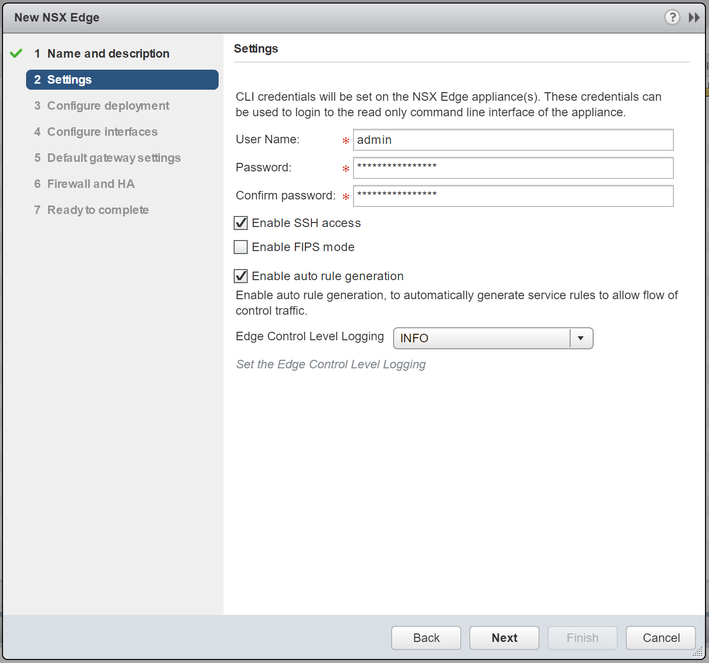
3. Configure the Appliance Size and Resources. Again, for lab purposes, the Compact appliance size is more than appropriate. When ready, click Next. 
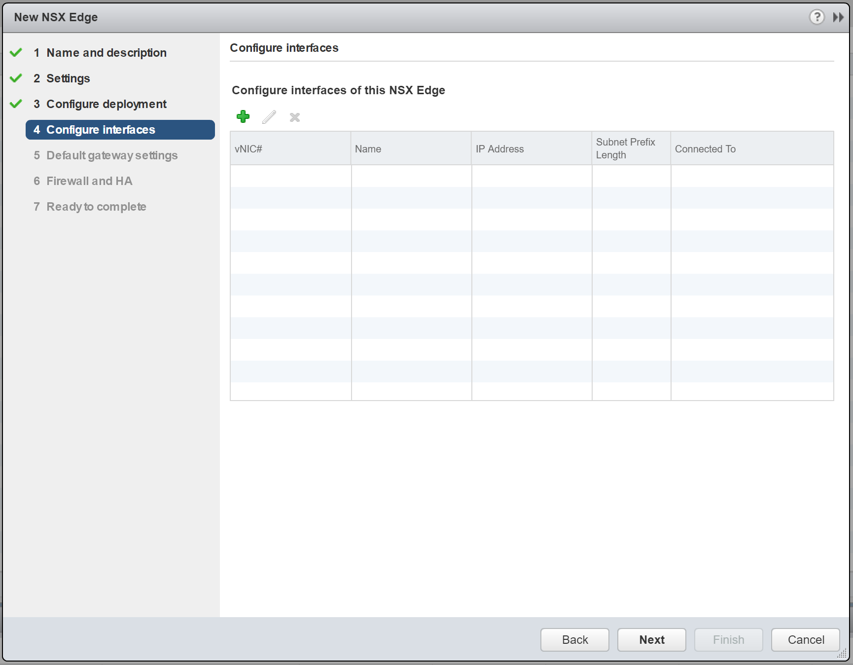
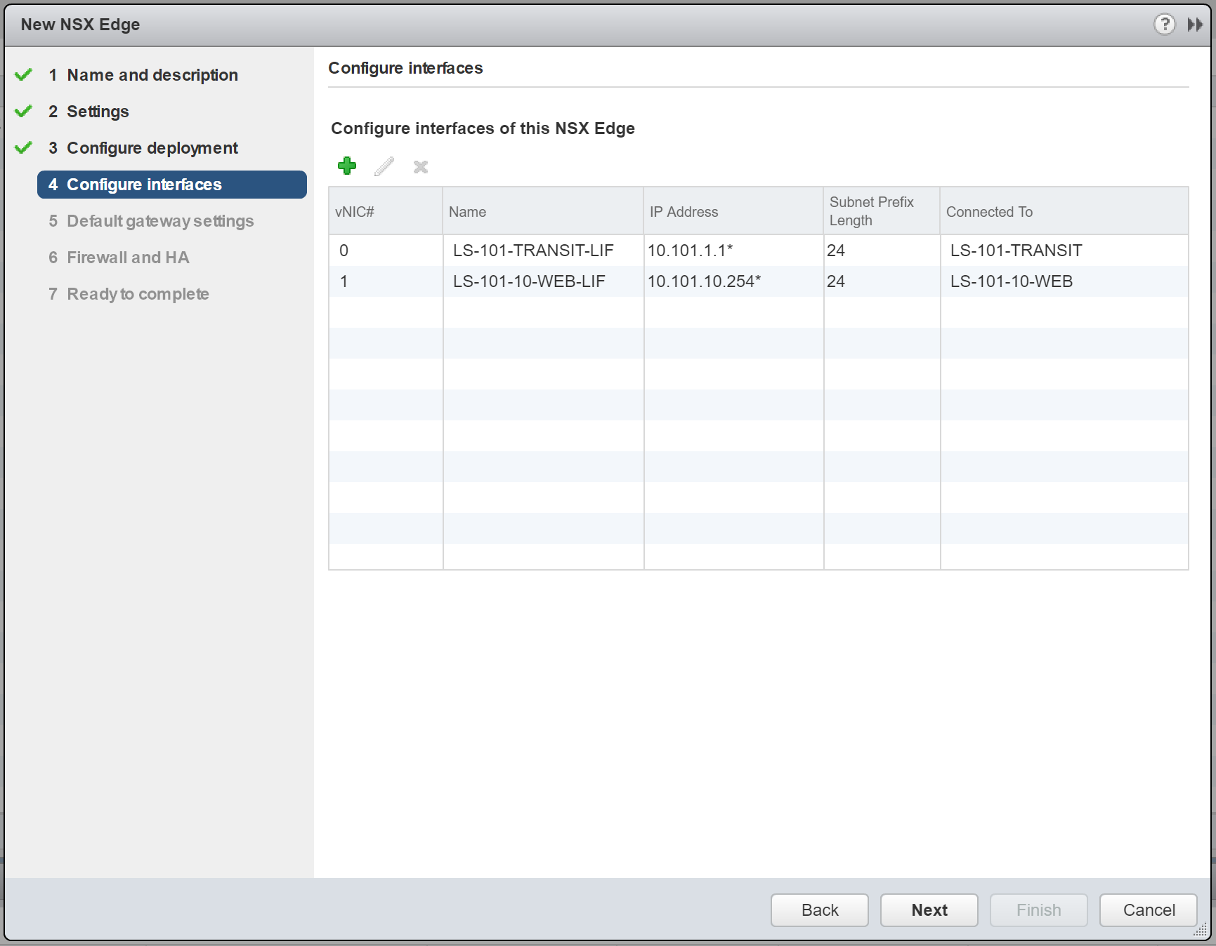
4. Next, we will configure two interfaces; one Uplink LIF, and one Internal LIF. Click the + button to begin.
5. First of all, create one Uplink LIF, assign it a Name, and connect it to the upstream Logical Switch (or to a VLAN by selecting the appropriate VDS). As per the topology diagram, the Uplink LIF will connect to the Logical Switch, LS-101-TRANSIT. Assign a Primary IP Address (this will be used as the load balancer’s virtual IP address) and, when ready, click OK.
Note – 10.101.1.1 has been assigned to the Uplink LIF and will be utilised in a future step as the virtual IP address of our new application pool. Additional/secondary IP addresses can be added and mapped to additional application pools (more on this in a later step), meaning one load balancer is capable of load balancing multiple applications.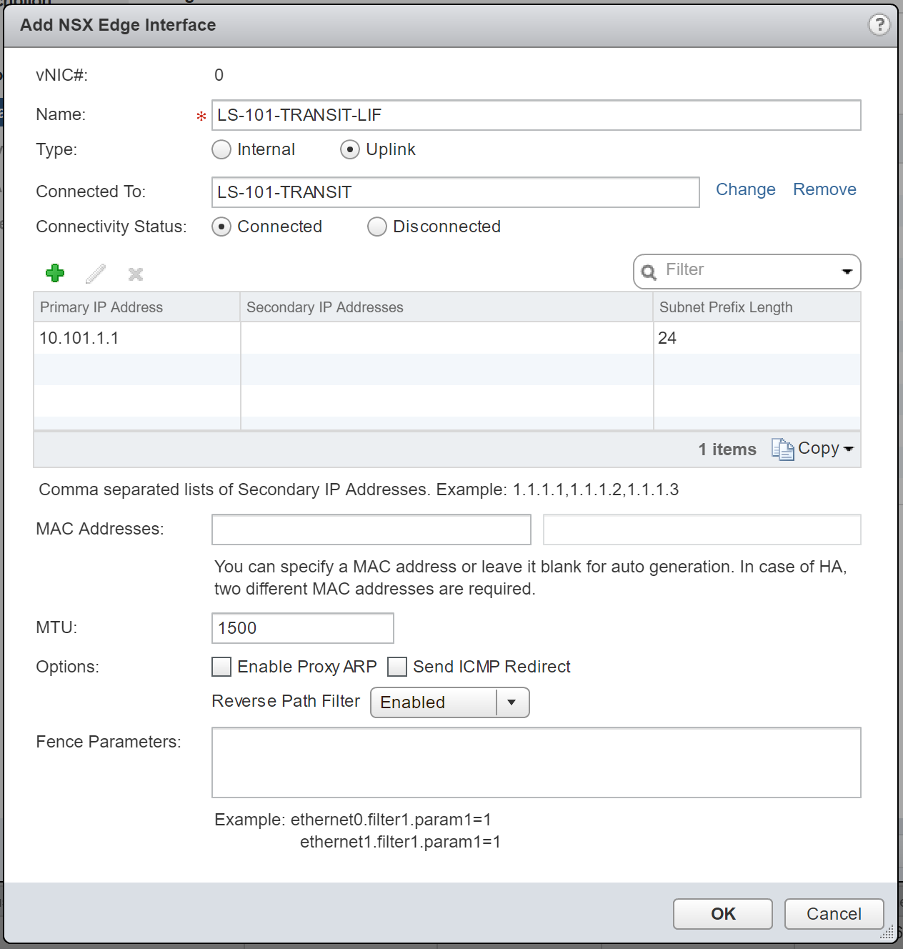
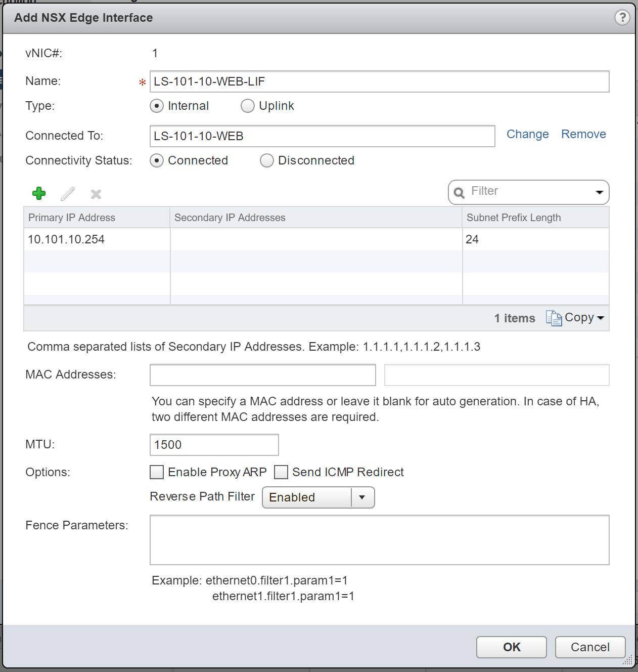
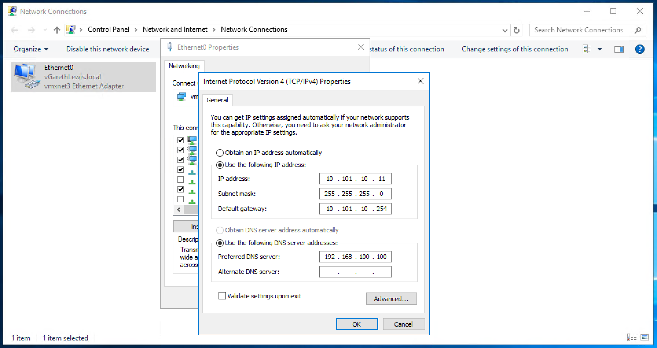
6. Repeat the previous step to create an Internal LIF, assign it a Name, and connect it to the downstream Logical Switch (LS-101-10-WEB) which houses our back-end servers. Assign a Primary IP Address (this will be used as the default gateway for all back-end servers) and, when ready, click OK.
7. Confirm the configuration and click Next.
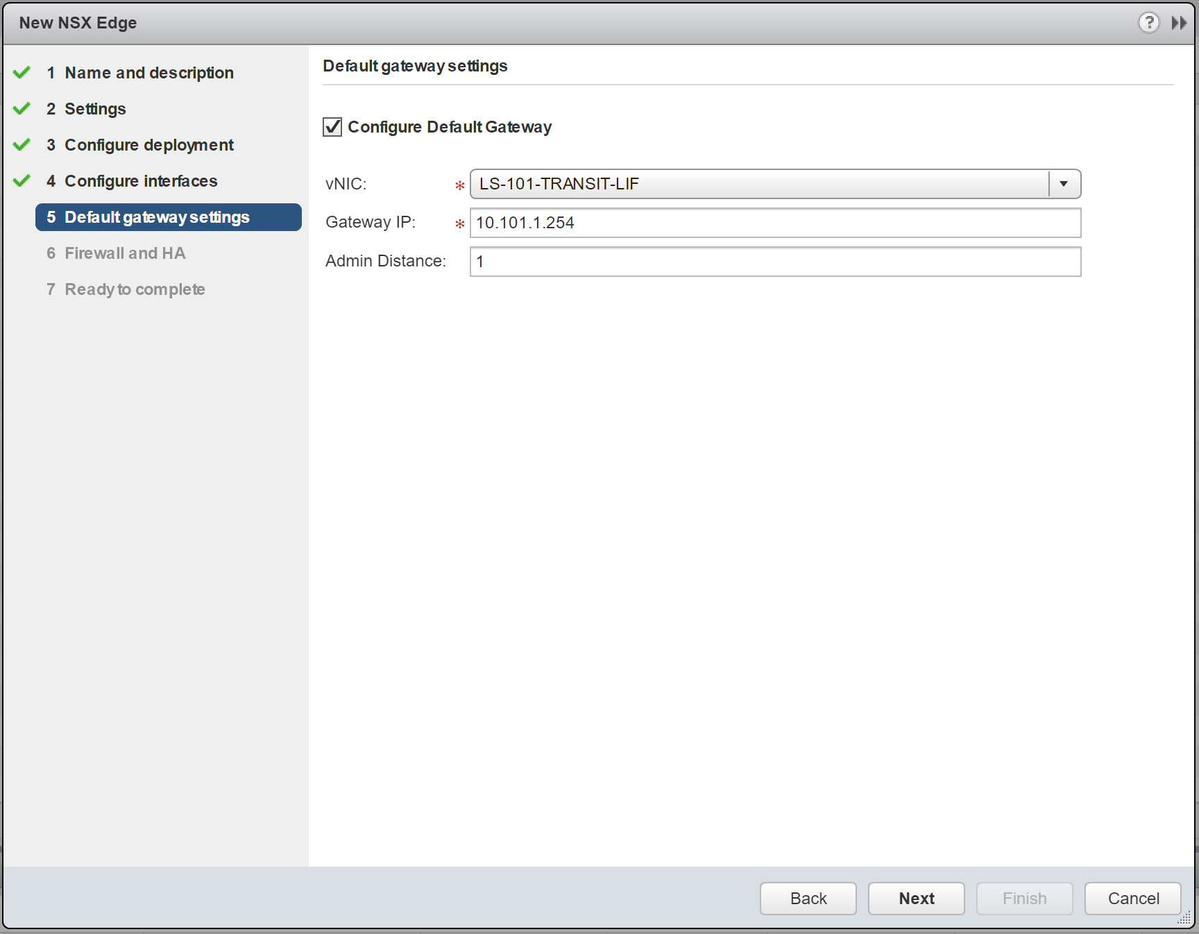
8. As per the topology diagram, the default gateway of this NSX Edge will be a perimeter NSX Edge (10.101.1.254). Configure accordingly and click Next.
9. For lab purposes, I will not configure any firewall policies. Also, as we are not deploying the appliance in HA mode, all HA parameters will be greyed-out. Click Next.

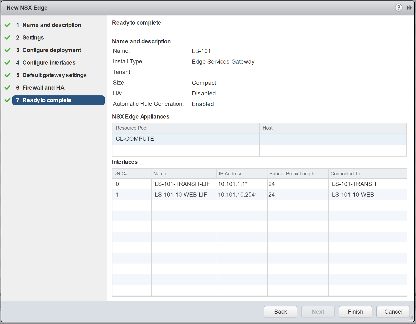
10. Confirm the NSX Edge configuration, and click Finish to deploy.
NSX Edge – Load Balancer Readiness Tasks
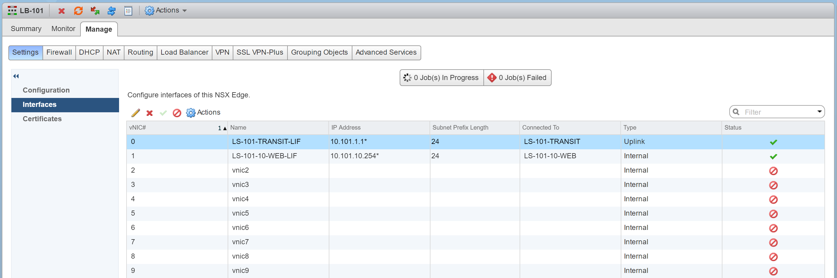
Firstly, let us review the interfaces of our new NSX Edge, of which, there are two:
- Uplink LIF (10.101.1.1) – This will act as our load balancer’s virtual IP address.
- Internal LIF (10.101.10.254) – This will be directly connected to the Logical Switch, LS-101-10-WEB, which houses our two back-end servers. The IP address of the Internal LIF will act as the default gateway to all back-end servers.
Secondly, as mentioned above, ensure to set the default gateway of all back-end servers to target the Internal LIF (10.101.10.254) of the NSX Edge.
Lastly, ensure connectivity to each step of the topology is successful.
NSX Edge – In-Line Load Balancer Configuration
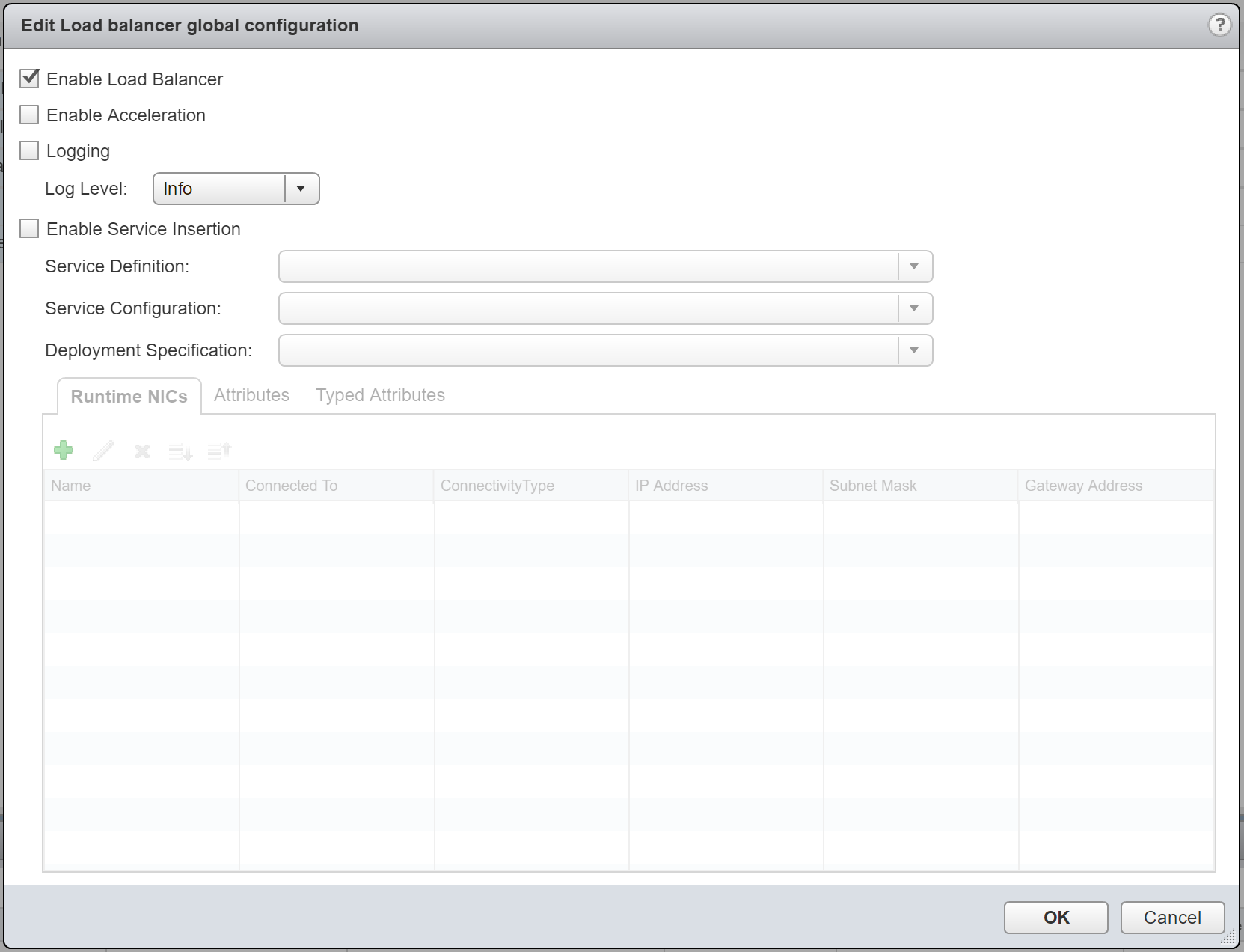
1. Browse to Manage > Load Balancer > Global Configuration and click Edit.
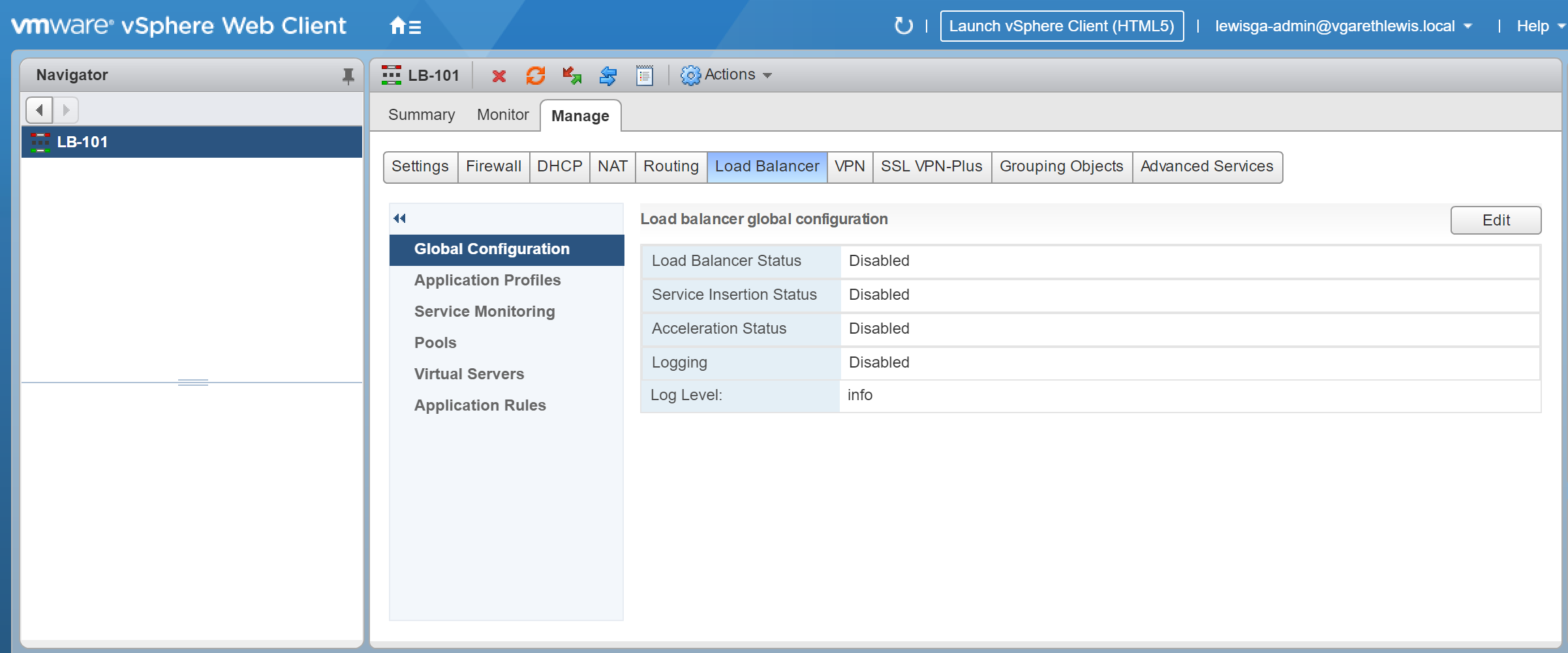
2. Ensure Enable Load Balancer is ticked, and click OK.
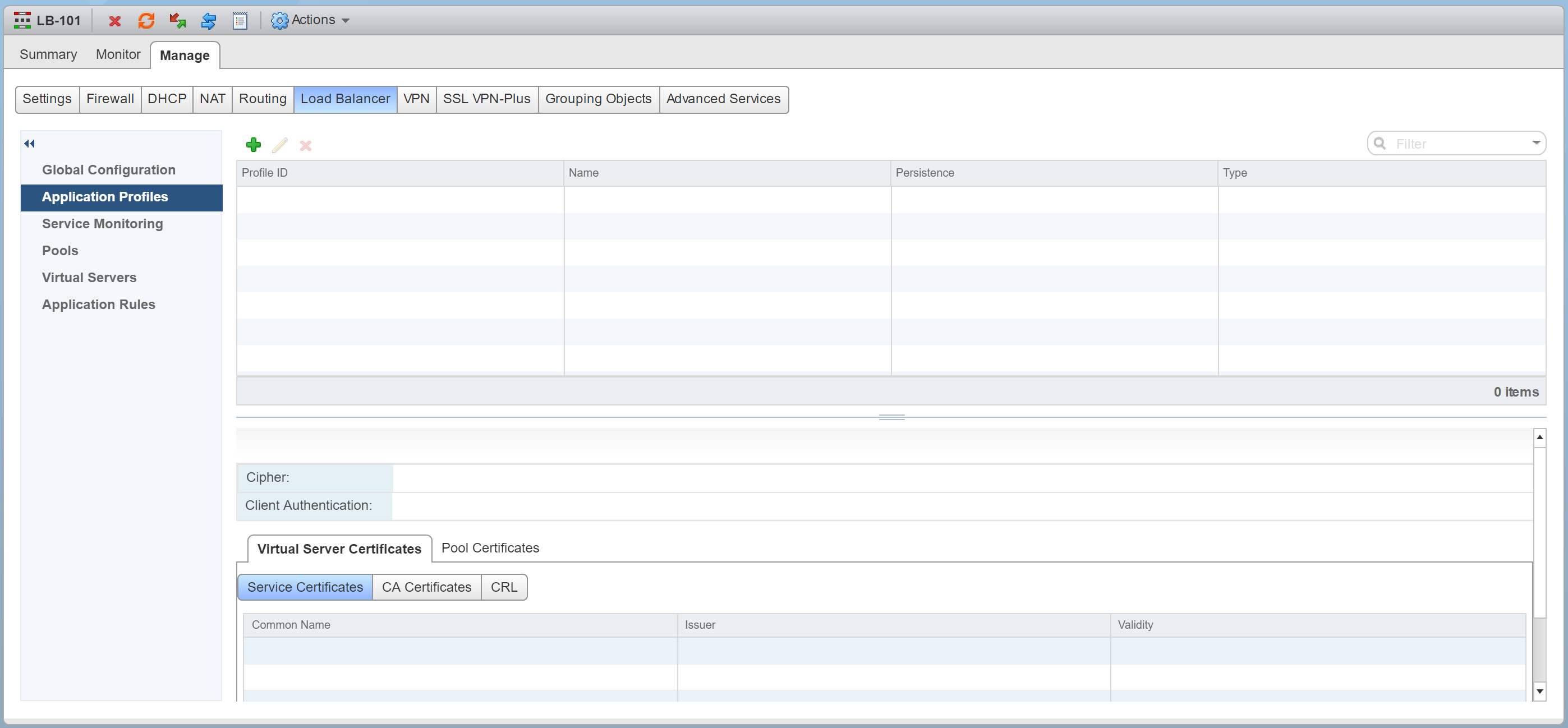
3. Browse to Manage > Load Balancer > Application Profiles and click +.
Application Profiles – An Application Profile is used to define the behaviour of a particular type of network traffic, and is associated with a virtual server (virtual IP address). The virtual server then processes traffic according to the values specified in the Application Profile. This allows us to perform traffic management tasks with greater ease and efficiency.
4. As mentioned previously, we are only interested in load balancing for resilience at the moment (we’ll expand on this as we progress with this series of NSX Edge Load Balancer posts). As such (and as detailed below), we will set the Application Profile Type to TCP.
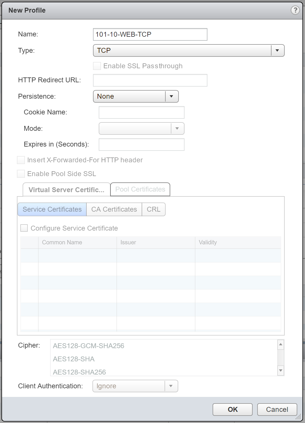
5. Confirm creation of the new Application Profile.

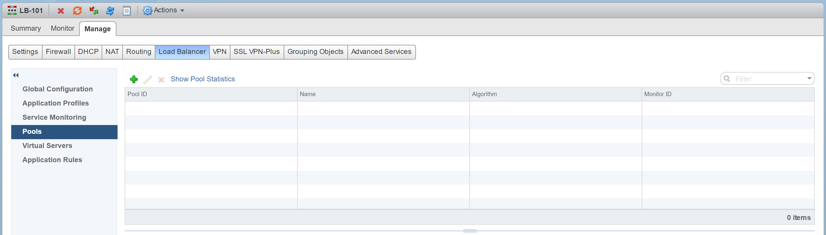
6. Browse to Manage > Load Balancer > Pools and click +.
Pools – A Pool is simply a group of back-end servers (aka, Members), and is configured with a load-balancing distribution method/algorithm. A service monitor (optional) can also be configured and, as this suggests, is used to perform health checks on its Members.
7. Give your new Pool a Name, Description, choose it’s distribution method/Algorithm, and Monitors.

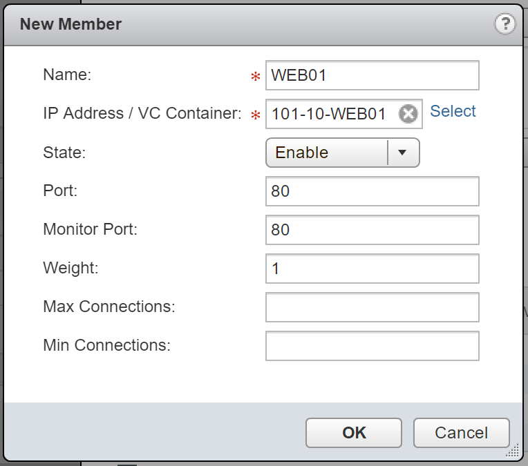
8. When ready, click + to add your back-end/member servers. For this, either click Select to choose a vSphere object, or simply type the destination IP address.
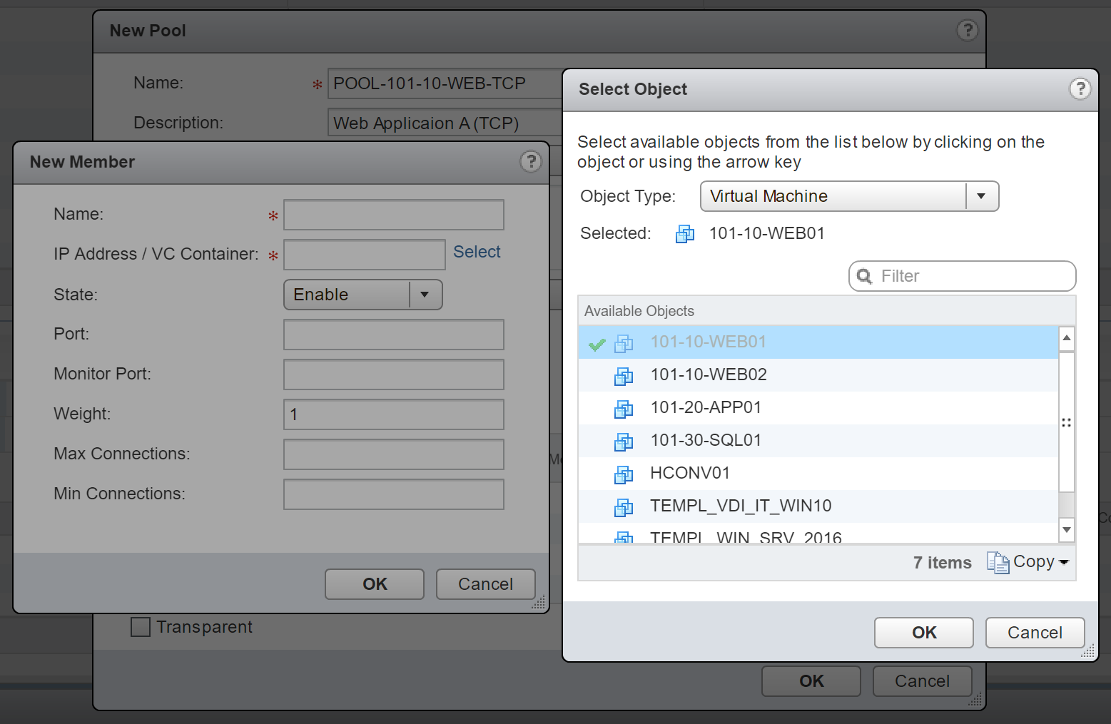
9. Define the Port (in this instance I am load-balancing HTTP/80 traffic) and Monitor Port (also port 80). When done, click OK.
10. Tick Transparent and click OK.
Note, as mentioned above, NSX Edges configured in Transparent mode will only perform DNAT on user traffic, with client IP addresses visible to all the back-end servers. As the NSX Edge will be acting as the default gateway for all back-end servers, it will be on the path of the server response.
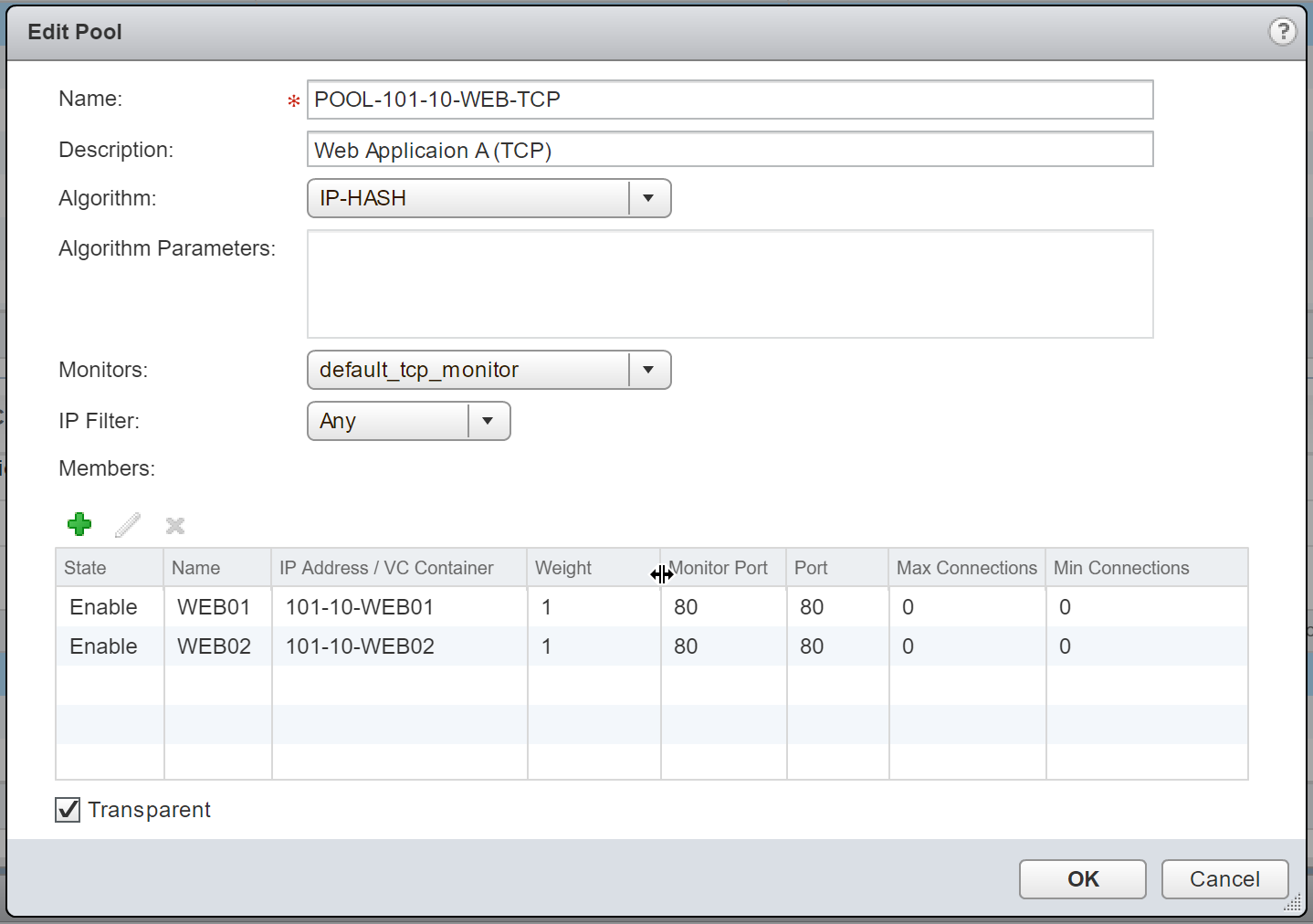
11. Confirm creation of the new Pool.
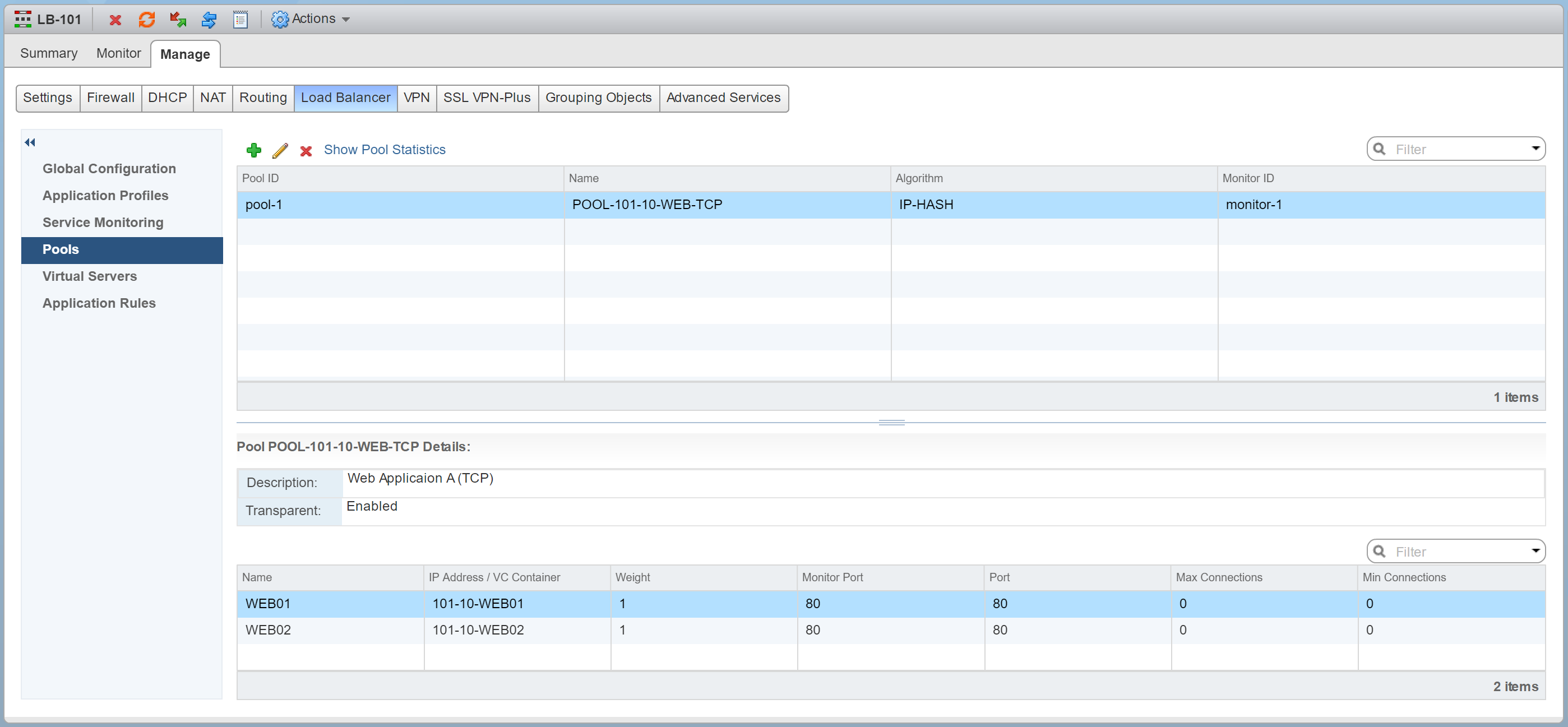
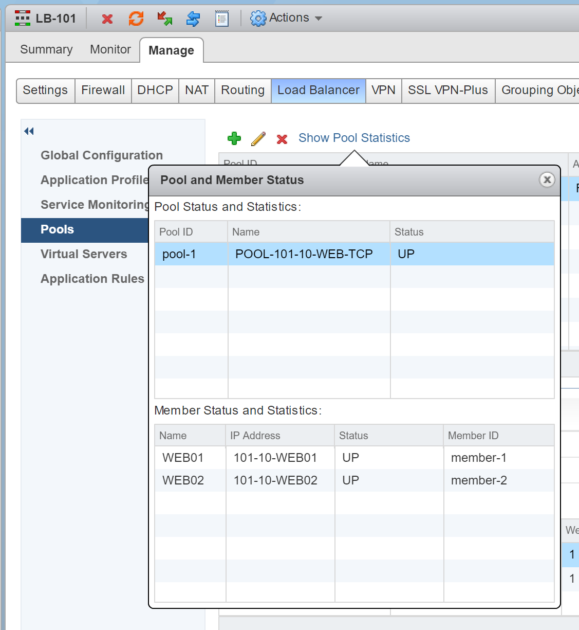
12. Check your newly created Pool’s health status by clicking Show Pool Statistics. The Status of both Pool and its Members should show UP.
13. Browse to Virtual Servers and click +.
14. From the Application Profile drop-down menu, select the recently created Application Profile, give the Virtual Server a Name and Description, and click Select IP Address to select the IP address which we allocated to the Uplink LIF in an earlier step (10.101.1.1).
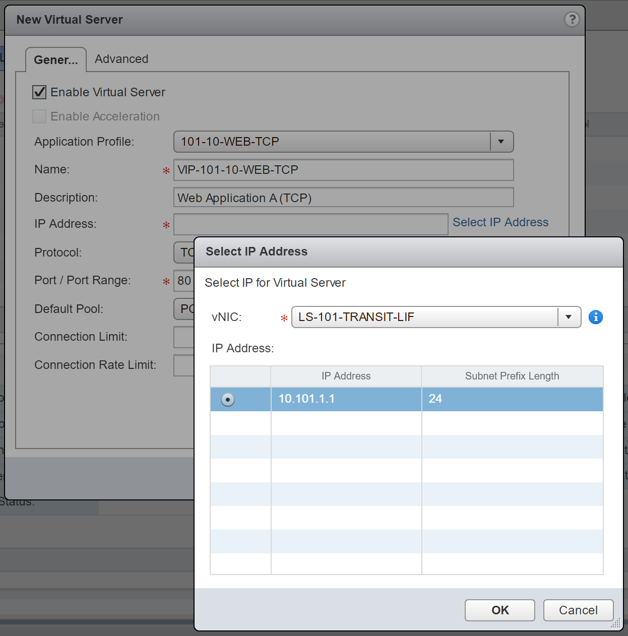
15. Lastly, set the Protocol to TCP, Port/Port Range to 80, and set the Default Pool to the pool we created in steps 6-11.
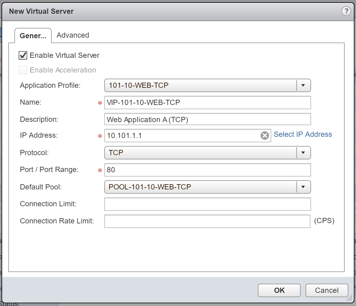
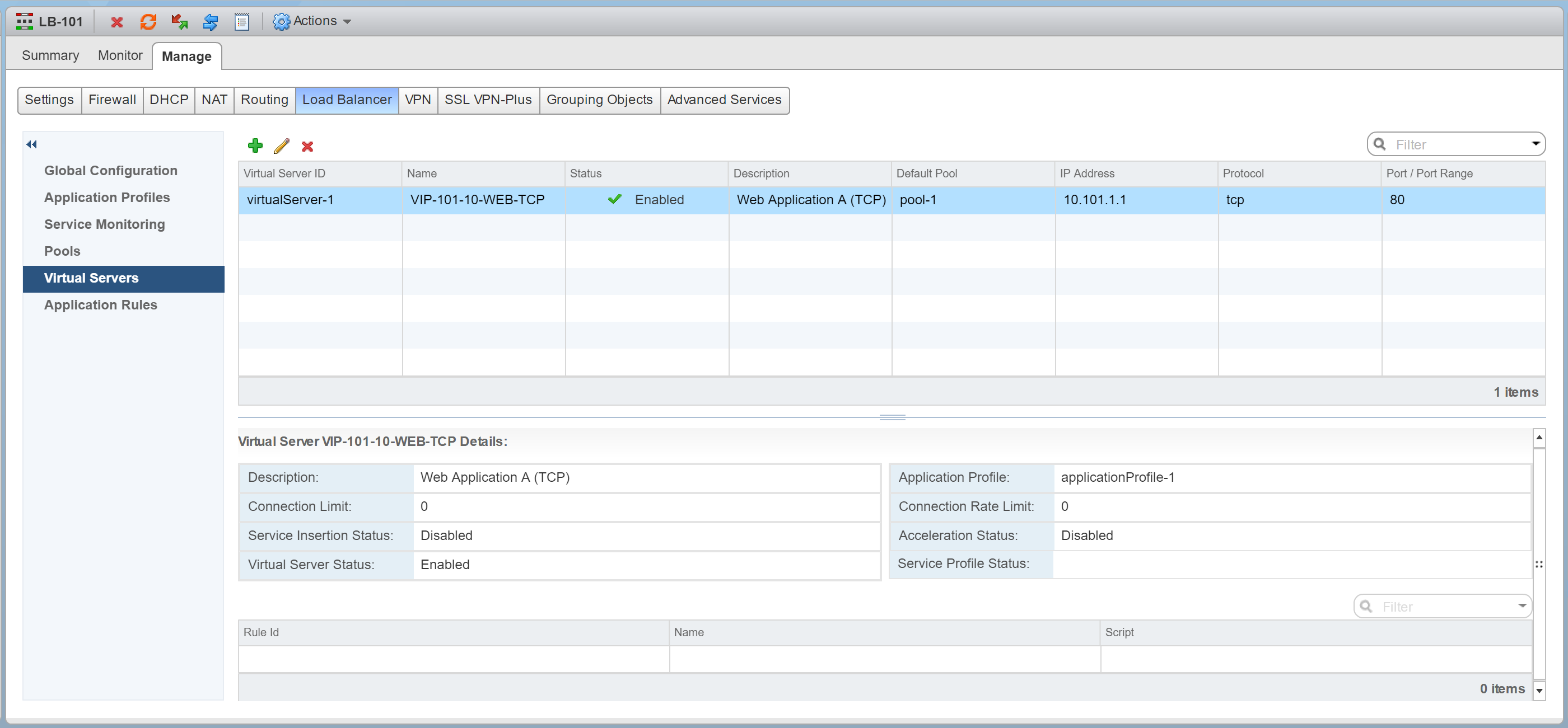
16. Confirm creation of the new Virtual Server.
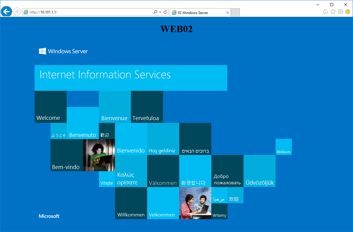
17. Finally, browse to the Virtual Server IP address (http://10.101.1.1) to confirm load-balancing to each of the Pool Members us successful. In the below screenshot, traffic is routed to the VM, 101-10-WEB01.

18. After a refresh, I am directed to 101-10-WEB02.
Conclusion
Having now covered both One-Armed (Proxy) and In-Line (Transparent) modes, we will look to cover further use cases and troubleshooting in future posts.
Leave a Reply