Where the NSX-T Distributed Firewall (DFW) provides stateful protection to workloads at the vNIC level from within for micro-segmentation of east-west traffic, the Gateway Firewall (GFW) provides centralised stateful protection of north-south traffic for perimeter firewalling. Depending on the use case, the GFW might secure traffic between physical and virtual servers, physical to physical servers, and within multi-tenant environments, DMZ’s or could be utilised for, for example, PCI compliance.
The GFW can be implemented per Gateway and is supported on both Tier-0 and Tier-1 Gateways. The GFW is also independent of the NSX-T DFW as it holds its own configuration and enforcement policies. Excitingly, we can also leverage the GFW to secure physical workloads housed on VLAN-backed networks via the Service Interface. This is particularly useful where customers are unable to utilise the VMware NSX-T Kernel Agent (think proprietary appliances/servers).
In this article, we take a look at the process of securing physical server workloads housed on VLAN-backed networks.
The below logical topology shows two Overlay Segments (Overlay Segment A and Overlay Segment B) housing several VMs. These VMs are, in turn, protected by the DFW. Also included in the topology is a VLAN-backed network (VLAN 80), which houses my test physical server. It is this physical server that we will secure by utilising the GFW.

Prerequisites
As the GFW is a stateful service, we must ensure our Gateway is housed on an appropriately sized Edge cluster. This is an important point if you choose to implement the GFW on a Tier-1 Gateway.
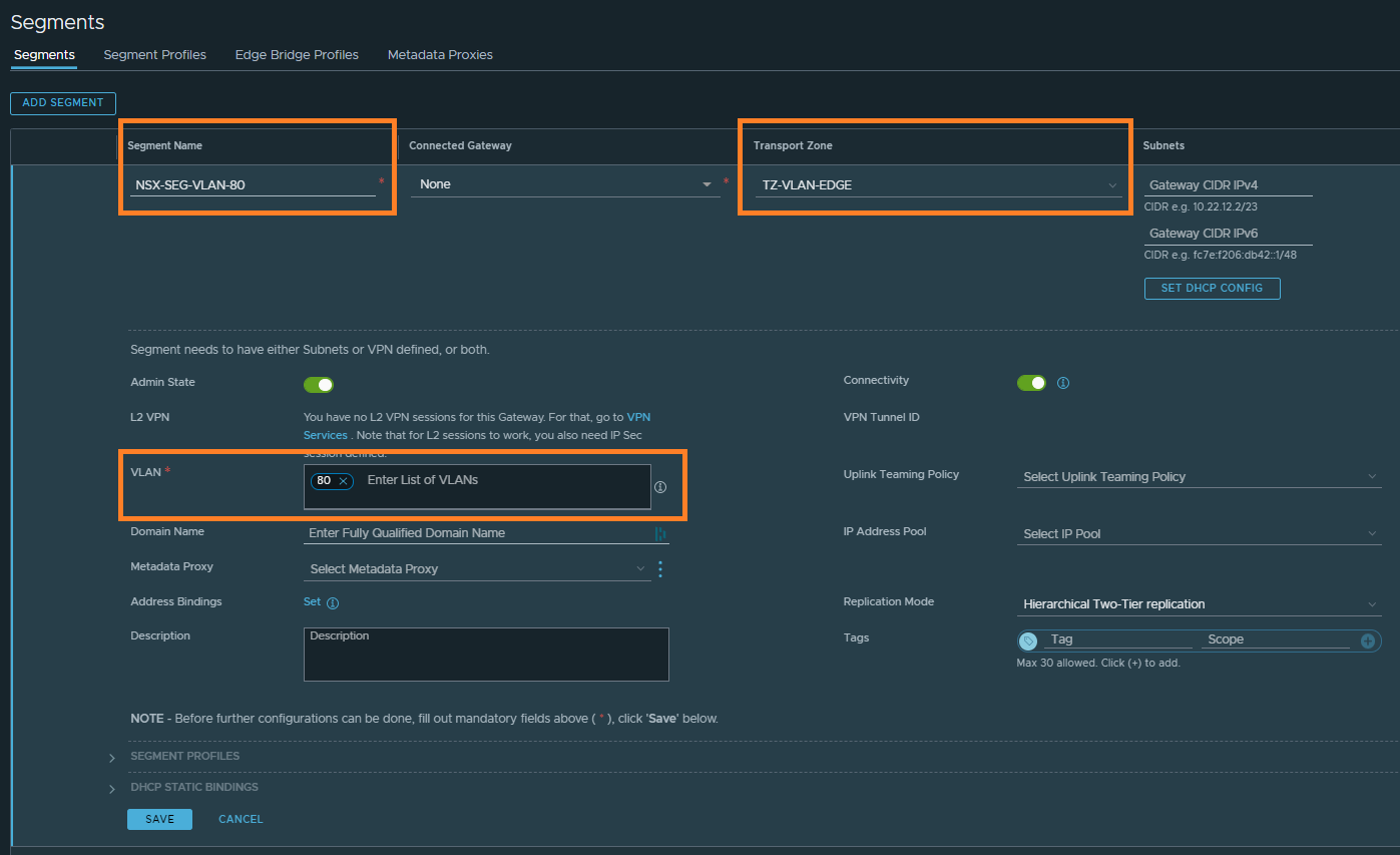
1. Create a new VLAN-backed Segment and associate it with the relevant Edge VLAN Transport Zone. This will be used by our Tier-1 Gateway’s Service Interface in a later step.
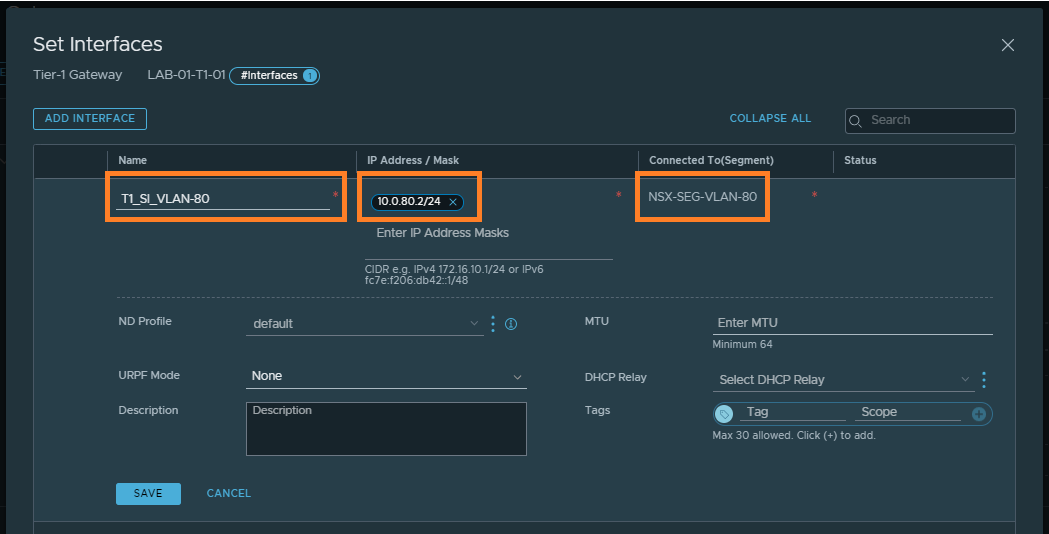
2. Browse to the Tier-1 Gateway and create a new Service Interface. Specify an IP address for the Service Interface (this will later be used as a default gateway by our physical server), and connect the Service Interface to the VLAN-backed Segment created in step 1.
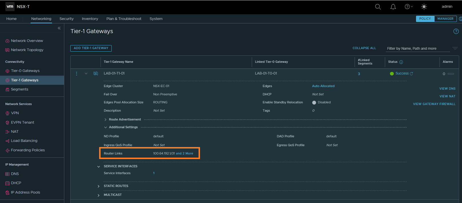
3. Next we need to identify the Router Link of our Tier-1 Gateway. This will be used in a later step to create a static route which, in turn, will be advertised to the physical network so that routing to the physical server traverses the Tier-0 and Tier-1 Gateways. In the below example, the Router Link is 100.64.192.1.
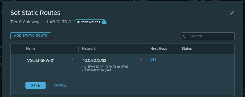
4. Browse to the Tier-0 Gateway and create a new static route, where the Network field equals the physical server’s IP address (in CIDR format) and the Next Hop is our Tier-1 Gateway’s Router Link.

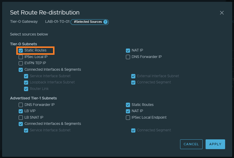
5. In my environment I’m using dynamic routing via BGP. As such, I need to ensure my Tier-0 Gateway is configured to advertise static routes.
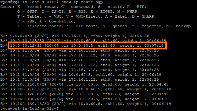
6. To validate the route is being advertised out to the physical network, I check the routing table on my leaf and spine switches. Note the inclusion of the route 10.0.80.12/32 via 10.0.60.5 (one of the Tier-0 Gateway Uplink Interfaces).
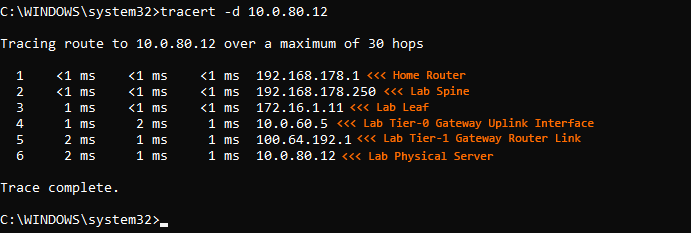
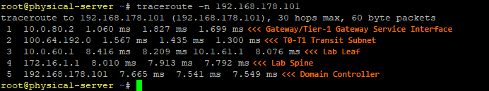
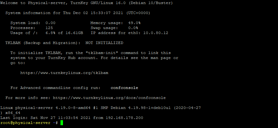
7. Finally, ensure the physical server is configured with the IP address defined in the static route (10.0.80.12), and with a default gateway that targets the Tier-1 Gateway Service Interface (10.0.80.2). Once complete, validate traffic to/from the physical device traverses the Tier-0 and Tier-1 Gateways.
Gateway Firewall Rules
Once routing via the Service Interface has been validated, we can begin looking at securing the physical server via the NSX-T Gateway Firewall.
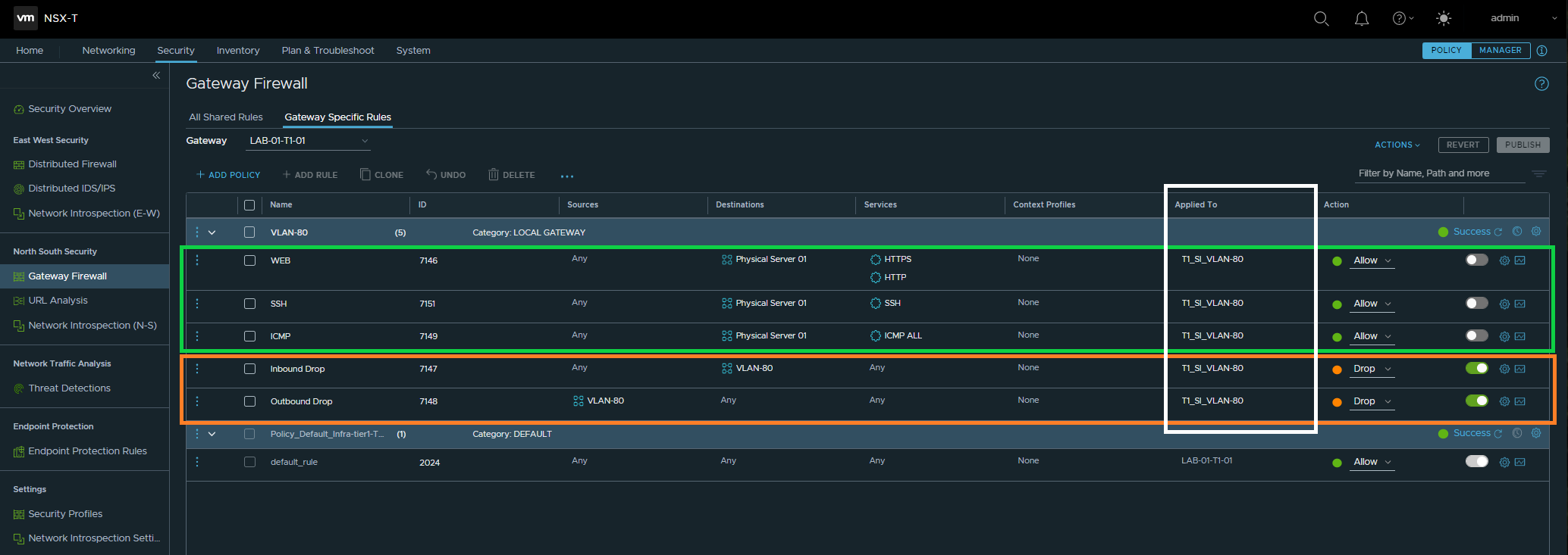
Browse to Security > North South Security > Gateway Firewall, select the relevant Tier-1 Gateway and begin to build out your Policies and Rules. To ensure my virtual workloads are unaffected, I opt to first create IP address-based inbound and outbound drop rules with a source/destination of VLAN in question. This will, essentially, apply zero-trust to the entire subnet.
In the below screenshot, you will note the below key points:
- Creation of two GFW drop rules targetting VLAN 80 (10.0.80.0/24)
- Creation of three GFW allow rules to enable access to the physical server via HTTP/HTTPS, SSH, and ICMP
- Rules are applied to the Service Interface
- The ‘allow’ rules are currently disabled for validation testing.
Validation
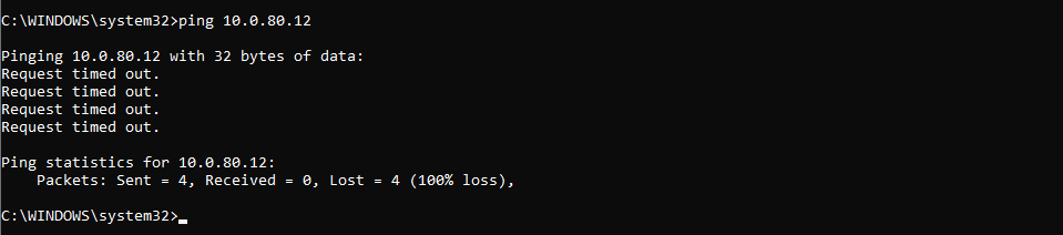
As mentioned above, my new allow rules are currently disabled, whilst all inbound/outbound traffic has been dropped. As such, let’s test access to the new physical server. In the below screenshot, note ICMP traffic is unsuccessful.
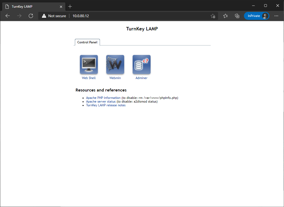
Finally, by enabling and publishing the three allow rules, I can now successfully HTTP/HTTPS, SSH, and ICMP traffic is now successful.

In Summary
In this article, we looked at the process of securing a physical server housed on VLAN-backed network by using the NSX-T Gateway Firewall. Alternatively, securing physical workloads could also be achieved via the NSX-T Kernel Agent, however, in this article/example, our physical workload was a proprietary appliance and which prevented us from installing any additional software, agents, etc. In this example, this is where the NSX-T GFW comes into it’s own.
Leave a Reply