I’ve worked with many customers over the years who are new to VMware NSX. This generally means a full design and deployment of NSX, but to be honest, a) that’s the easy bit and b) it doesn’t give the customer much in the way of immediate value. After all, all we’ve done is deploy a software-defined networking platform and generally peered it with the physical environment.
The value begins once the Customer’s workload is actually housed on an NSX Segment. This is where we begin discussing workload migrations from physical VLANs/VDS port groups to NSX Overlay Segments. ‘Easy’ you say, ‘just migrate the virtual machines and re-IP, right’? That’s one option, however, what if the Customer has thousands of VMs? What if these VMs host mission-critical applications or applications which are prone to issues following re-IPing? Sometimes this option just isn’t feasible.
The best solution for this Customer might be to migrate workloads and retain IP addressing. We can achieve this by migrating the entire physical network into VMware NSX, however, we can also achieve this by creating a VMware NSX Edge Bridge, which effectively creates a layer-2 extension between a physical VLAN and an NSX Overlay Segment.
In this article, we will detail a number of migration scenarios before detailing the process of deploying and configuring a layer 2 extension via NSX Edge Bridge.
Technologies Used
- vCenter Server 8.0.0.10100
- VMware ESXi, 8.0.0, 20842819
- VMware NSX 4.0.1.1.0.20598726
Migration Scenarios
Firstly, let’s talk about migration scenarios, as we have a few options:
Option 1 – Physical Network Cutover to NSX
Where possible, this is often the easiest and quickest approach, however, if there are a substantial number of physical workloads also present on the network, it may take time to move these off.
To migrate the entire network, we simply shut down the physical gateway/SVI and create a new NSX Overlay Segment using the same subnet and gateway IP address. The Customer will preferably be using dynamic routing which, in turn, will advertise the new Overlay Segment to the physical fabric via a Tier-0 Gateway. Once routing tables are updated, we can migrate all VMs from a legacy VLAN-backed VDS port group to the new NSX Overlay Segment. All in one go. Easy.
Option 2 – Phased Migration of Physical Network to NSX via Edge Bridge
Where a customer prefers to move workloads into NSX piecemeal or application-by-application, this can be achieved by simply extending a physical network via an NSX Edge Bridge. In this scenario, we create a layer 2 extension between a physical VLAN and NSX Overlay Segment and gradually bring virtual workloads across. However, until the physical gateway is migrated into NSX, tromboning between the virtual environment to the physical environment will occur, which is not something we want to allow to continue for too long a period.
When ready, the physical gateway is migrated to NSX in the same manner as Option 1 (above), and the bridge is removed.
In this article, we will focus on Option 2, the process for which is detailed below.
Environment Overview & High-Level Steps
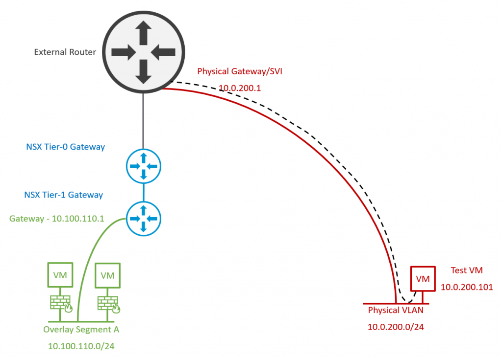
1. Let’s take a look at the current environment. VMware NSX has been deployed for two-tier logical routing, with BGP configured between Tier-0 Gateway and physical routers. The environment has already deployed a new virtual workload to NSX Overlay Segments (10.100.110.0/24, left/green), however, we have identified a legacy physical VLAN (10.0.200.0/24, right/red) which has been flagged for migration.
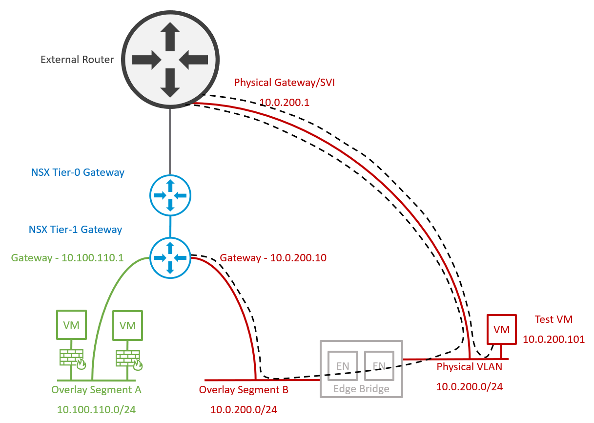
2. Edge Nodes are deployed/re-used to house edge bridge profiles. An Overlay Segment is created with a dummy/temporary gateway IP address in readiness for virtual workload migration, and configured with the Edge Bridge, extending the Overlay Segment to the physical VLAN. Note – Traffic from the new Overlay Segment still routes via the Edge Bridge and out to the physical fabric via the physical gateway/SVI.
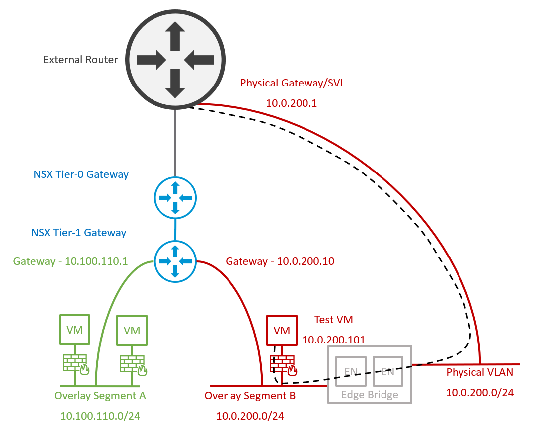
3. VMs are migrated to the new Overlay Segment. Note – Traffic from the new Overlay Segment still routes via the Edge Bridge and out to the physical fabric via the physical gateway/SVI.
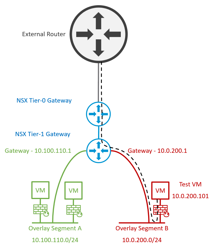
4. Finally, the physical gateway/SVI is removed from the physical fabric, and the NSX Overlay Segment’s gateway IP address is amended to reuse the legacy VLAN gateway IP. This concludes the migration activities, after which the Edge Bridge can be removed.
Prerequisites
Firstly, we require a trunked port group which will be utilised by our Edge nodes for bridge connectivity. Dependent on your environment, a full and detailed list of options is available via Configure an Edge VM for Bridging (vmware.com).
ESXi 6.7 or Later and VDS 6.6.0 or Later
Option 1 – Enable MAC learning on the distributed port group by utilising PowerCLI (see William Lam’s great post, Native MAC Learning in vSphere 6.7 removes the need for Promiscuous mode for Nested ESXi (williamlam.com)).
Option 2 – As we are leveraging VMware NSX (formerly NSX-T), the preferred option in this scenario is to utilise an NSX VLAN Segment, for which we simply create and attach a new Segment Profile configured to allow MAC learning. This NSX VLAN Segment can then be used for our edge uplinks.
ESXi 8.0 or Later and VDS 8.0 or Later
With VDS 8.0, things get a lot easier, and we can now utilise a distributed port group configured to allow MAC learning directly from the vSphere UI.
As I am utilising vSphere 8 and, in conjunction, VDS 8.0, I will opt to use this method in the article.
Firstly, I need to create a new trunked port group, add the VLAN IDs which will participate in the trunk, and configure its security settings to enable MAC Learning with Allow Unicast Flooding also enabled.
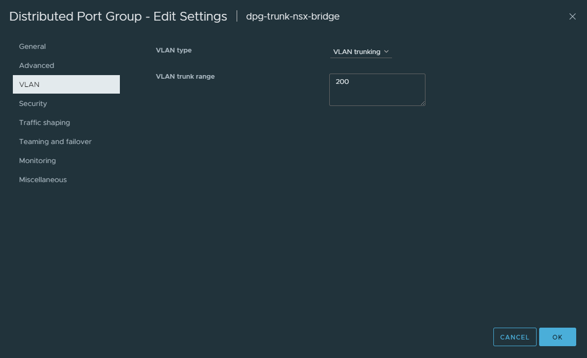

My Edge nodes will only be allocated a single uplink. As such, I configure the Failover Order accordingly.

Edge Bridge Deployment and Configuration
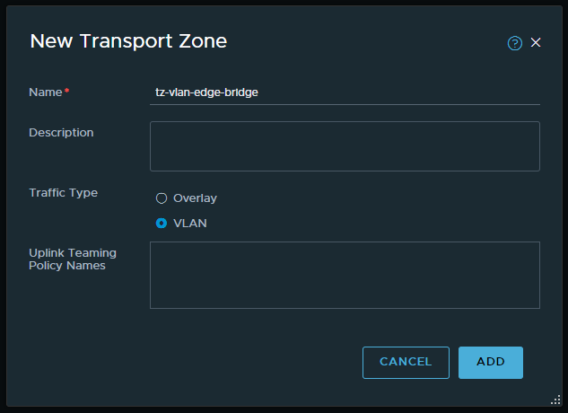
1. Create a new Transport Zone for bridge use.
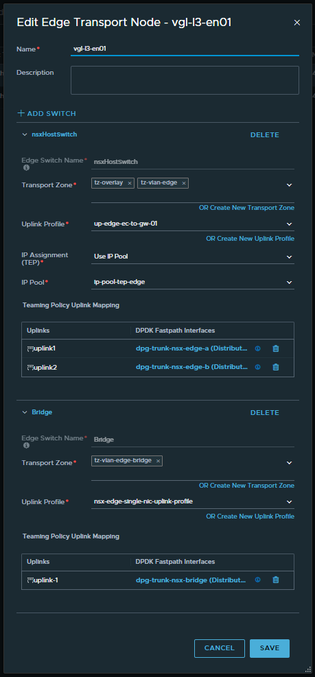
2. In a production environment, I would opt to deploy new NSX edge nodes to host bridge functionality. This would be preferable where you might expect a lot of traffic to traverse the bridge. In my lab environment, I will simply use my existing edge nodes (which facilitate N/S routing and Tier-0 Gateway placement) and add an additional N-VDS/HostSwitch for bridging.
Note – My Bridge N-VDS connects to the previously created trunk port group with MAC Learning enabled. Also, the uplink profile used here does not require a transport VLAN, so I simply opt to use the default nsx-edge-single-nic-uplink-profile.
Complete this task for all edge nodes in the edge cluster.
3. Browse to Networking > Connectivity > Segments > Profiles > Edge Bridge Profiles, and create an Edge Bridge Profile utilising your Edge Cluster.
Note here the Fail Over mode. Preemptive or Non Preemptive? In the event that the primary edge node experiences a failure, the backup node will always be elevated to primary. However, the Fail Over mode gives us two options when it comes to post-recovery operations:
- Preemptive – When the original primary node recovers, it will resume primary operations.
- Non Preemptive – When the original primary node recovers, it will NOT resume primary operations.
With a Preemptive Fail Over configuration, we can ensure deterministic routing by pinning the bridged traffic to a specific edge node. For example, should we have a requirement to bridge multiple VLANs (e.g., 200 and 210), we would create two (2) Edge Bridge Profiles with a configuration as per below. This would enable us to balance the bridged traffic more efficiently by pinning a specific bridged VLAN to a specific edge node.
- Bridge-Profile-01 – Used for VLAN 200
- Primary Node – Edge Node 01
- Backup Node – Edge Node 02
- Bridge-Profile-02 – Used for VLAN 210
- Primary Node – Edge Node 02
- Backup Node – Edge Node 01
In my lab environment, I am only stretching one (1) VLAN (VLAN 200), so I only require Non Preemptive.

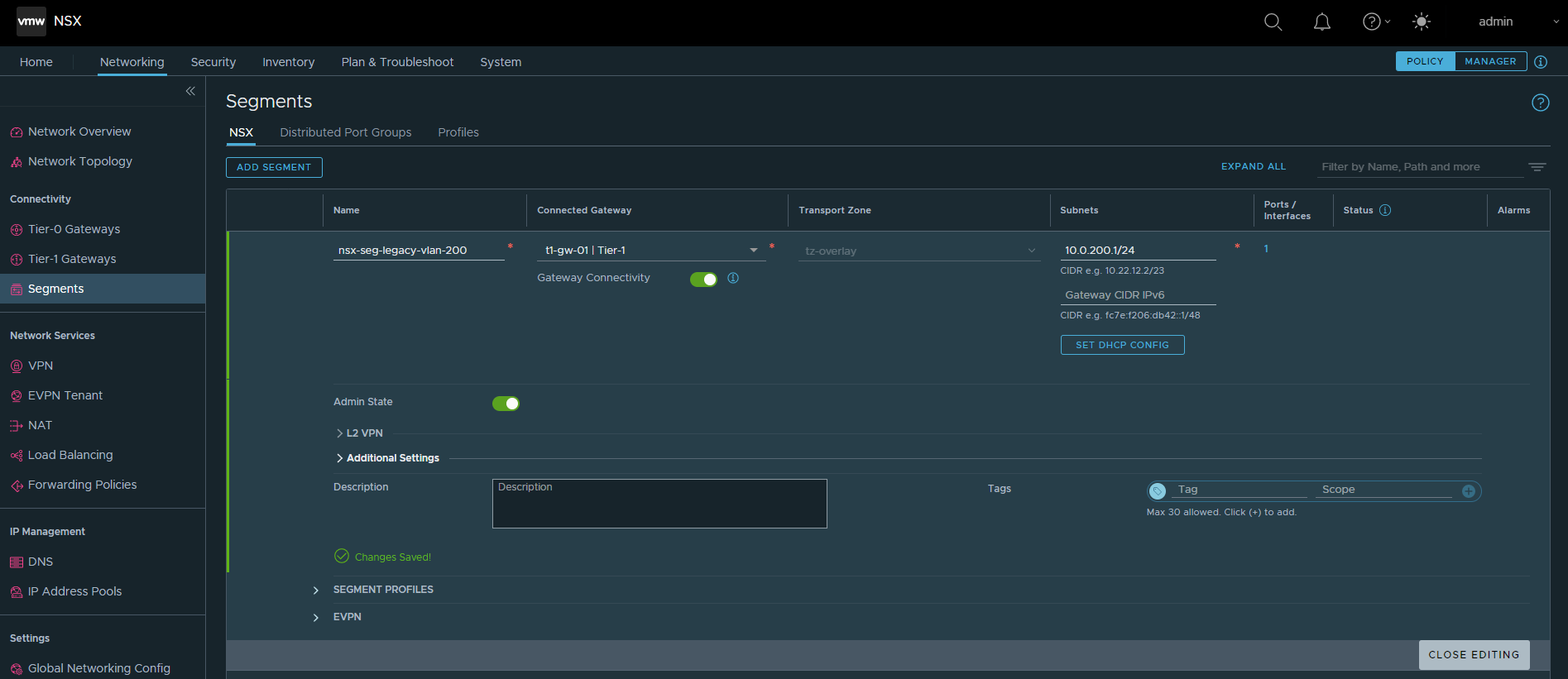
4. Create a new Overlay Segment and configure its Gateway with an unused IP address. The physical gateway/SVI in my lab environment is 10.0.200.1/24. In the below example, I allocate 10.0.200.10/24 to the NSX Overlay Segment’s Gateway. Ensure that Gateway Connectivity is disabled.
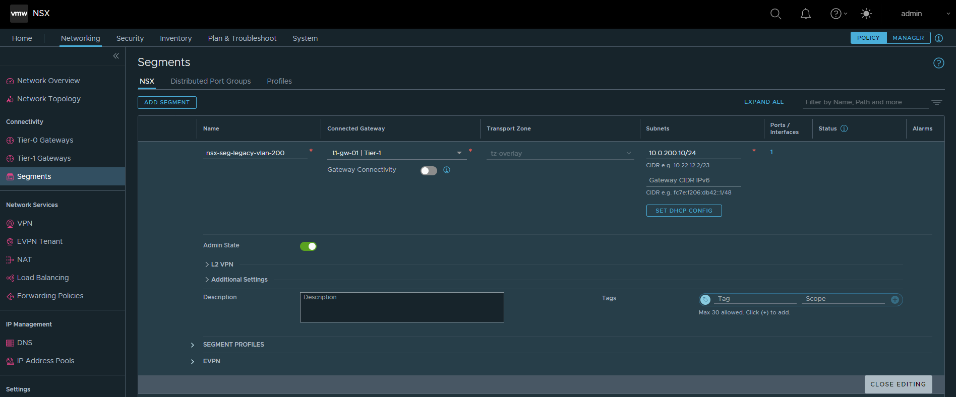
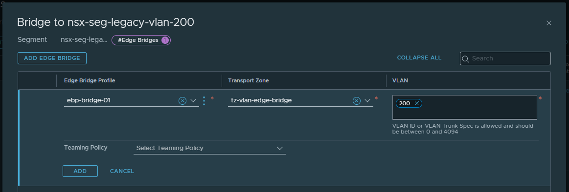
Save, continue editing, browse to Additional Settings > Edge Bridges and click Set. Select the recently created Edge Bridge Profile and bridge Transport Zone, and allocate the VLAN ID you wish to stretch. When ready, click Add.
Pre-Migration Validation & Testing
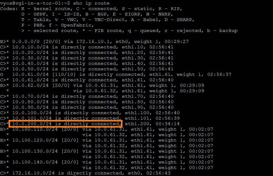
From my top-of-rack switches, notice the directly connected 10.0.200.0/24 network. Note this for later.
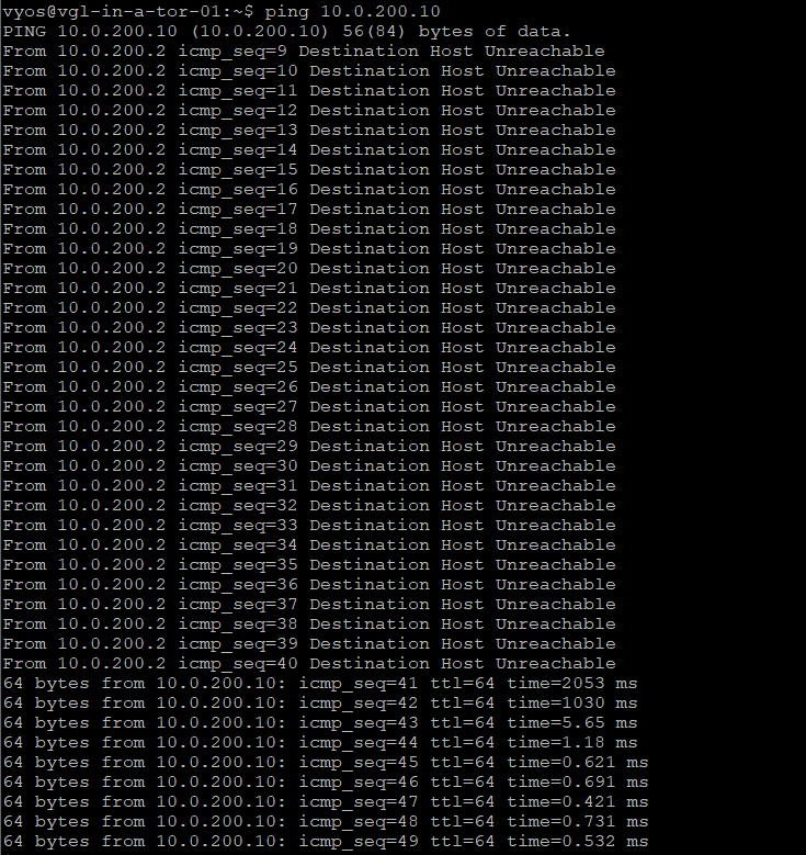
ICMP traffic from one of my top-of-rack switches to the Overlay Segment’s gateway (10.0.200.10) is successful once the Edge Bridge Profile is applied.
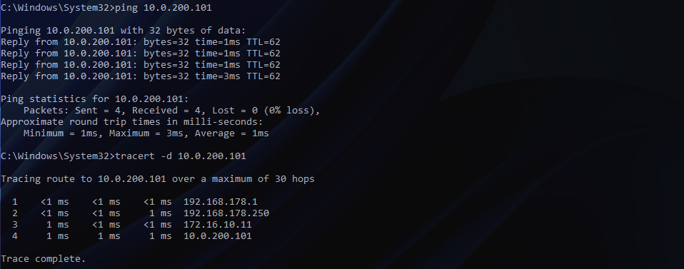
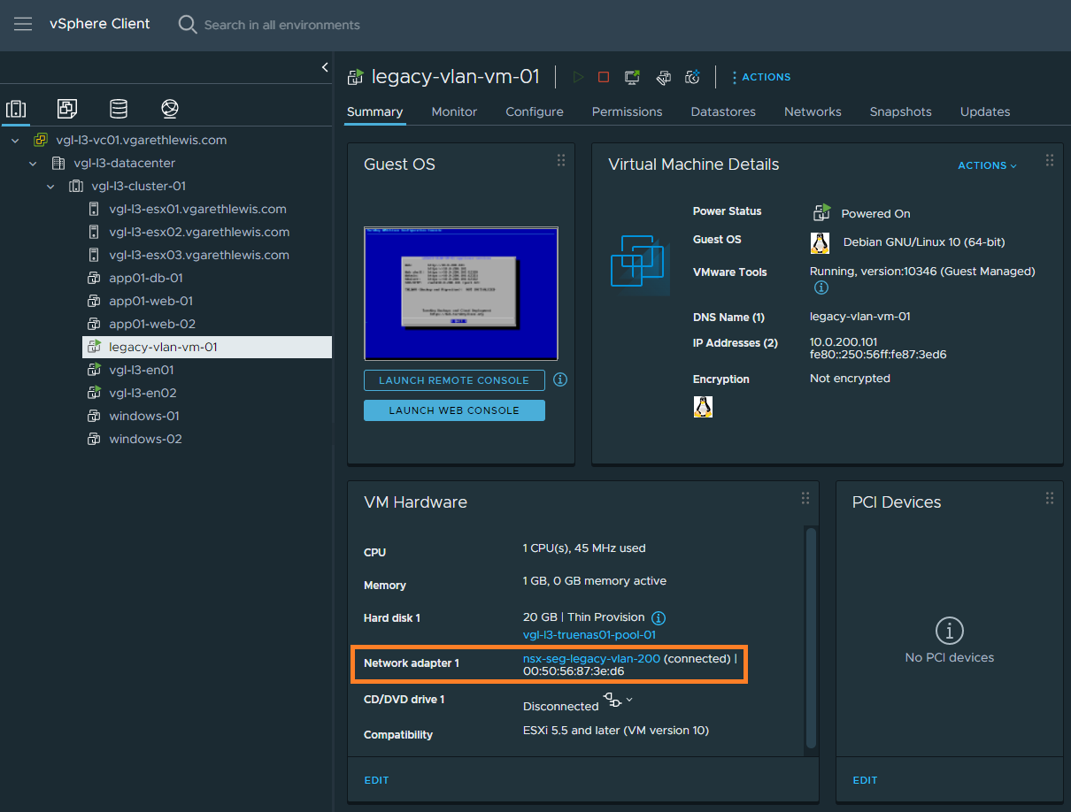
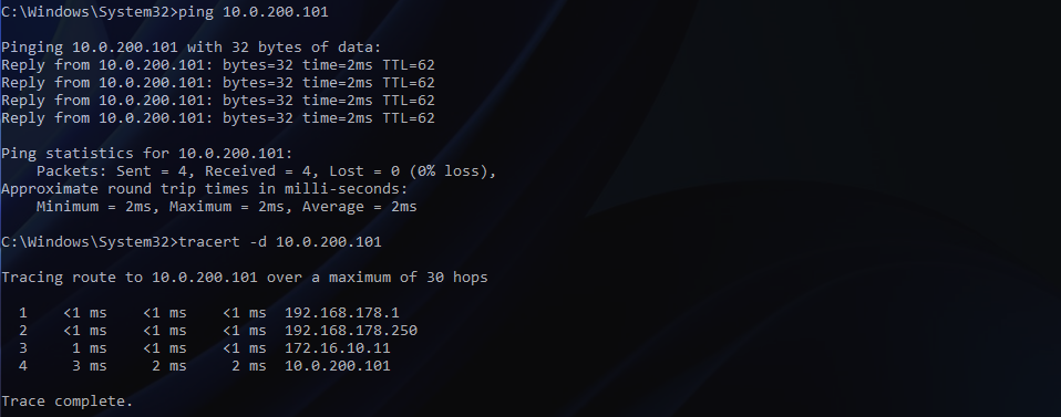
Let’s confirm routing to our test VM on the physical VLAN 200. You’ll note that traffic from an external device to the VM routes via one of my top-of-rack switches (172.16.10.11) which holds the VLAN’s gateway/SVI, as expected.
Migration
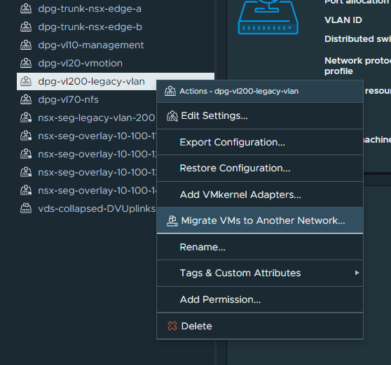
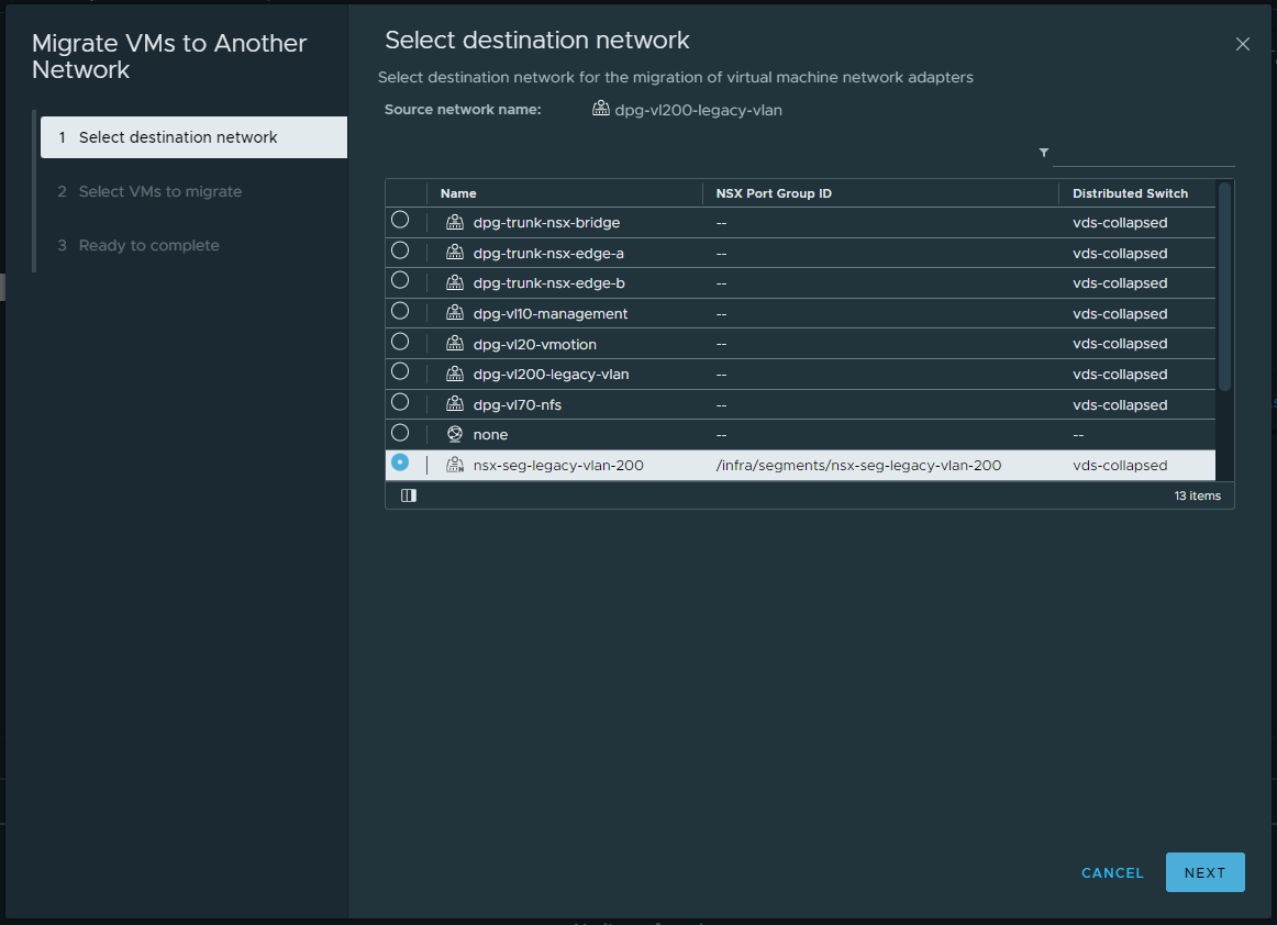
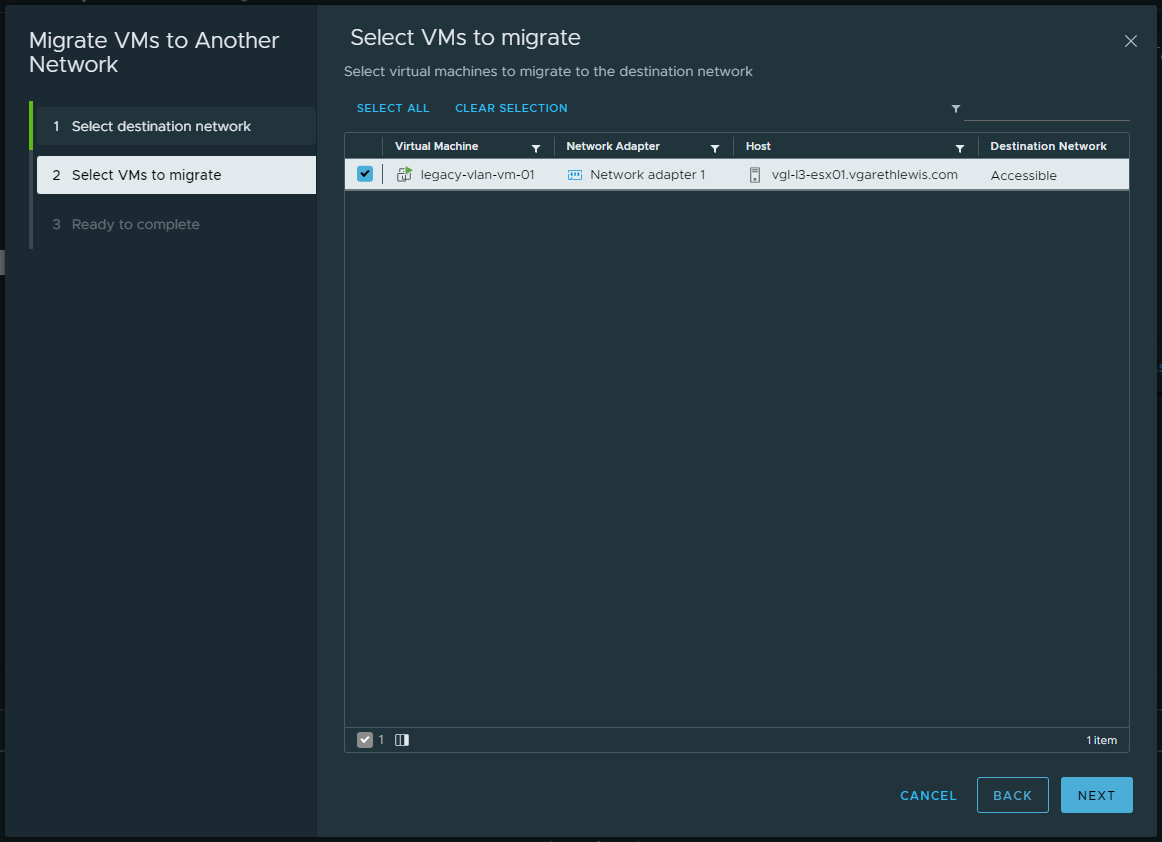
1. Migrate all VMs housed on the physical VLAN (VDS distributed port group) to the new bridged NSX-T Overlay Segment. In my lab environment, I only utilise one VM for testing. In reality, we can simply select all VMs.
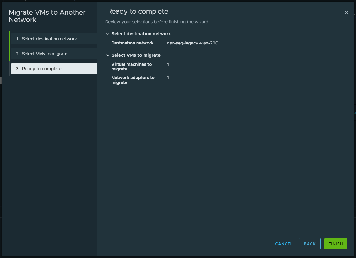
Note – There is no change in routing, as the gateway still resides on the physical fabric.
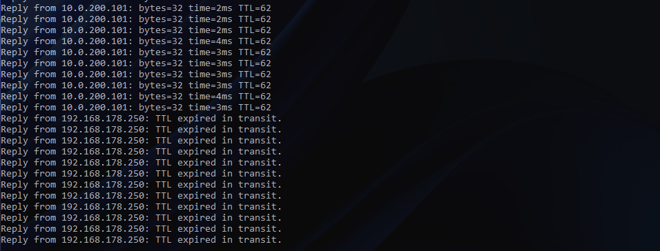
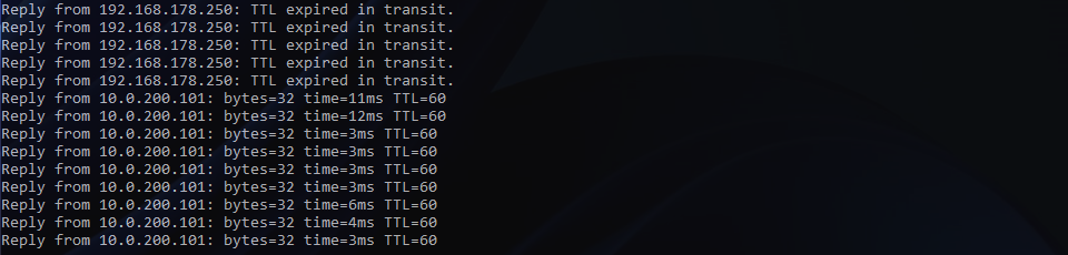
IMPORTANT – At this point, the Edge Bridge can remain in place as physical workloads may still be housed on the VLAN. Once all physical and virtual workloads have been migrated (days/weeks/months), we remove the physical (10.0.200.0/24) SVI from our physical switches. This will result in a loss of connectivity to all VMs. The below screenshot shows the drop in connectivity to my VM.
As expected, the previously connected network (10.0.200.0/24) is dropped from the routing table on my top-of-rack switches.
Finally, we change the new Overlay Segment’s gateway from .10 to .1 (.1 was previously used as the physical gateway/SVI) and enable Gateway Connectivity. When ready, click Save.
Post-Migration Validation & Testing
By enabling the Gateway Connectivity, the routing table on my top-of-rack switches has been successfully updated. The NSX Overlay Segment is now being advertised in BGP via my Tier-0 Gateway’s uplink interfaces:
- Edge Node 1 fp-eth0 = 10.0.61.31
- Edge Node 2 fp-eth0 = 10.0.61.32
- Edge Node 1 fp-eth1 = 10.0.62.31
- Edge Node 2 fp-eth1 = 10.0.62.32
The below screenshot shows top-of-rack 01 only.

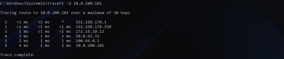
VM connectivity will now be restored, and a traceroute will show the new route via my Tier-0 Gateway.
Clean-Up Tasks
Finally, we can remove the Edge Bridge from the NSX Overlay Segment, rinse, and repeat for any other VLANs flagged for migration.
Once all migration activities are complete, we can remove any/all Edge Bridge Profiles and remove the additional HostSwitch added to both Edge Nodes.
In Summary
In this article, we discussed a number of migration scenarios before detailing the process of extending a physical VLAN to a VMware NSX Overlay Segment by deploying and configuring an NSX Edge Bridge. This solution fits best when a Customer needs to migrate workloads and retain IP addressing.
Leave a Reply