In this article, we take a look at VMware NSX-T Data Center Multisite and, more specifically, the failover/recovery procedure for an NSX-T environment spanning two sites in an active/standby deployment. This is also known as the NSX-T Multisite disaster recovery use case.
Constraints
First of all, we need to understand our environment, as well as the current constraints:
- Licensing prevents the use of NSX-T Federation (only available in Enterprise Plus). As such, we will utilise NSX-T Multisite.
- There is no stretched vSphere management cluster or stretched management VLAN between our two locations (Site A and Site B). As a result, the recovery of the NSX-T management data planes must be handled manually.
Before we dive into the failover steps in detail, let’s learn a little more about our environment and take a high-level look at the process needed to restore networking and security.
Failure Scenario
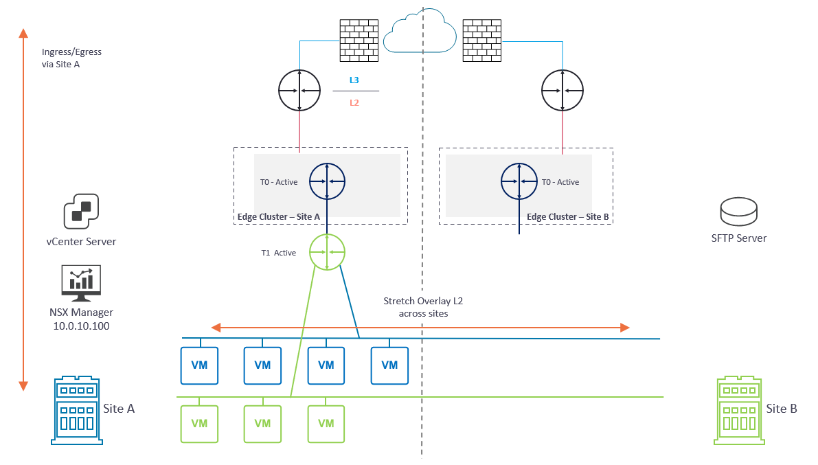
In Diagram 1 below, please note several key points:
- Each location (Site A and Site B) houses a dedicated active/active NSX-T Edge Cluster.
- Each NSX-T Edge Cluster houses a dedicated Tier-0 Gateway which, in turn, is connected to the respective site’s physical fabric.
- BGP has been configured between each Tier-0 Gateway and its respective upstream physical router.
- An overlay Transport Zone spans Site A and Site B and enables two NSX-T overlay networks to span both sites via a global Tier-1 Gateway.
- Blue Network – 10.100.110.0/24
- Green Network – 10.100.120.0/24
- The global Tier-1 Gateway is connected to the Tier-0 Gateway in Site A. As such, ingress/egress traffic is via Site A only.
- The NSX Manager in Site A manages the management plane. In a production environment, this would be an NSX Manager Cluster.
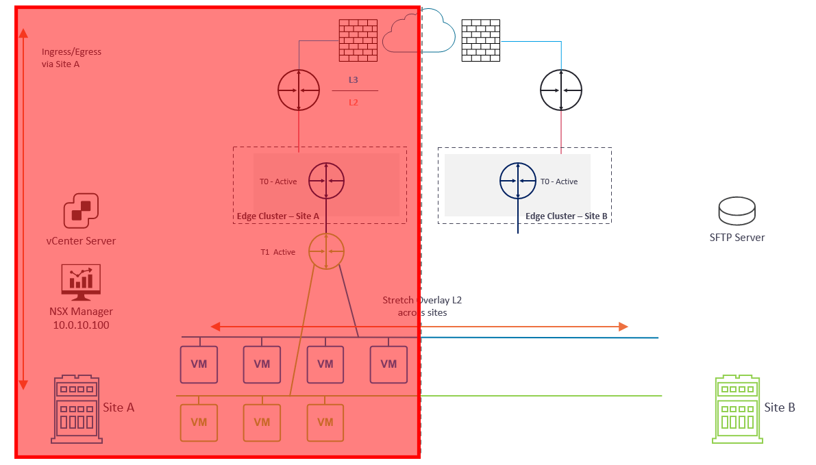
In the event of a failure at Site A (Diagram 2) (and due to no stretched vSphere management cluster or stretched management VLAN mentioned earlier) both management and data plane traffic is lost.
Our primary objective is to restore access to the management plane. To do this we will deploy a new NSX Manager appliance to Site B (Diagram 3) and restore the configuration from backup (more on backups a little later). As part of the restore process, we will build out the NSX Cluster.
Once access to the management plane is restored, we can access our NSX Manager and attach the global Tier-1 Gateway to the Tier-0 Gateway in Site B (Diagram 3). The Tier-0 Gateway at Site B will then advertise the downstream overlay networks to the upstream physical fabric and, once new routing information is learned, data plane traffic is restored. Ingress/egress traffic now flows via Site B.
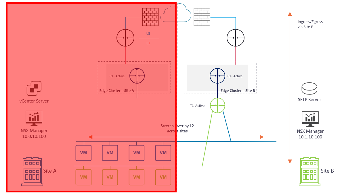
At this point, we have successfully completed the recovery of NSX-T to Site B.
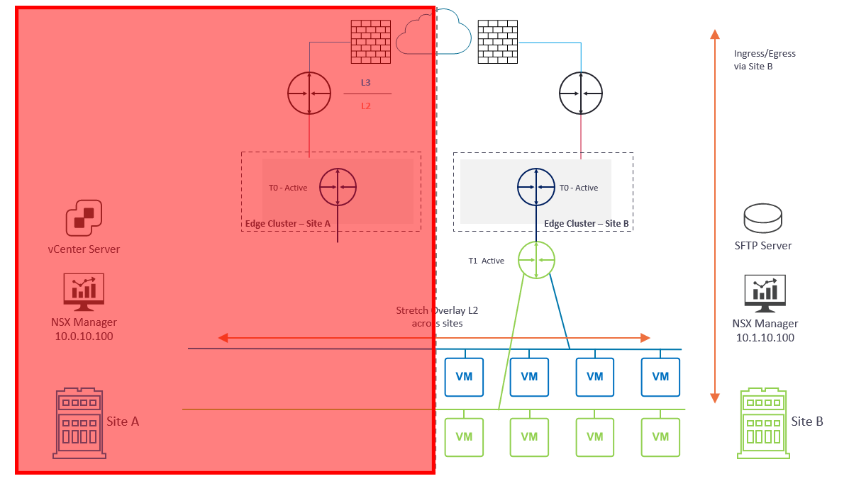
As an option, we may wish to utilise VMware Site Recovery Manager (SRM) to recover VM workloads to Site B in order to restore access to our applications (Diagram 4). Please note, the SRM failover process is not detailed in this article.
Prerequisites
Backups…Backups…Backups
I’ve mentioned backups several times so far. If you are yet to configure your NSX Manager backups, stop reading, and go do this now. Simply visit my previous post, VMware NSX-T Data Center Backups.
If you’re reading this article because you’re experiencing an NSX outage and haven’t been performing NSX Manager backups…sorry, I really feel for you.
Secondly, the backup target needs to be an SFTP server which, for obvious reasons, should be located in the DR site (i.e., Site B). Having already lost access to NSX, also losing access to your backups would be double-bad.
To reiterate one final time – ensure your NSX Manager backups are running automatically with continuous backup, and ensure they are validated and tested regularly—more details for which are covered in my previous post, VMware NSX-T Data Center Backups.
DNS
Ensure forward and reverse records exist for all NSX Managers (ideally with a short TTL (for example, 5 minutes)) in Site A.
In this article, I am utilising a single NSX Manager and, under normal operations, the Site A IP address detailed below is utilised. When it comes to failing over to Site B, a new IP address is required, unless you have a stretched layer-2 network between sites.
| NSX Manager | Site A | Site B |
| vgl-nsxt-01.vgarethlewis.com | 10.0.10.100 | 10.1.10.100 |
NSX Manager FQDN Registration
Enabling FQDN (DNS) on NSX Managers is required for NSX-T Multisite. By default, all transport nodes (host and edge) access the NSX Managers by IP address. As such, we need to ensure all transport nodes access the NSX Managers via FQDN, and not the IP address. When the NSX Manager(s) are restored to a secondary site using different IP addresses, we amend DNS to target the new NSX Managers.
FQDN registration must be in place before any failover activity occurs and should be part of your NSX-T Multisite design.
For more information, please see my previous post, VMware NSX-T Manager FQDN Registration.
Inter-site Communication
- The bandwidth must be at least 1 Gbps, and the latency (RTT) must be less than 150 ms.
- MTU must be at least 1600. 9000 is recommended.
Failover Procedure
The procedure itself can be broken down into 8 simple steps.
- Deploy a new NSX-T Manager to Site B
- Amend DNS to target the new NSX-T Manager
- Implement NSX-T Manager FQDN registration on the new NSX-T Manager
- Configure NSX-T Manager backup, initiate restore from backup, and build out the NSX Cluster
- Validate Transport Node to NSX Manager connectivity
- Attach global Tier-1 Gateway to secondary site Tier-0 Gateway and validate dynamic routing via BGP
- Validate routing and connectivity to/from overlay VMs in Site B
1. Deploy a New NSX-T Manager to Site B
As mentioned above, our first task is to deploy a new NSX Manager appliance to Site B by configuring the appliance with the required credentials and a suitable IP address (in our case, the new IP will be 10.1.10.100). This process is quite simple, so I won’t cover the deployment steps in this article.
Important, the new appliance deployed to Site B must match the version of the inoperable appliance in Site A.
2. Amend DNS
Next, amend all DNS records to point at the new NSX Manager in Site B.
| NSX Manager | Site A | Site B |
| vgl-nsxt-01.vgarethlewis.com | 10.0.10.100 | 10.1.10.100 |
3. NSX-T Manager FQDN Registration
As mentioned above, we need to configure the new NSX Manager to be accessed via FQDN by all transport nodes. This process is detailed in my previous post, VMware NSX-T Manager FQDN Registration.
4. Configure NSX-T Manager Backup, Restore Configuration and Build Out NSX CLuster
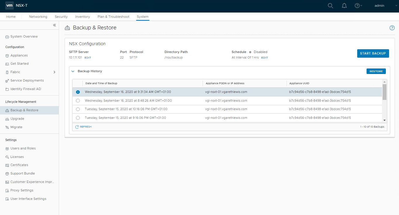
Login to the new NSX Manager and browse to System > Lifecycle Management > Backup & Restore, and configure the backup to access your SFTP Server. Once complete, you’ll be able to access your previous backups (as per the below screenshot). When ready, select the required backup and click Restore.
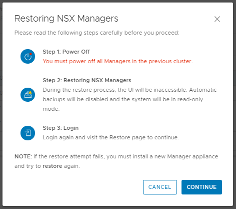
When prompted, ensure all previous NSX Managers are powered off. As we’ve lost access to Site A, this isn’t possible, but in a lab/POC environment, make sure you power them down when prompted. When ready, click Continue.
The status of the restore operation will now be displayed and should be monitored. This can take some time, so now might be a good time to grab a coffee.
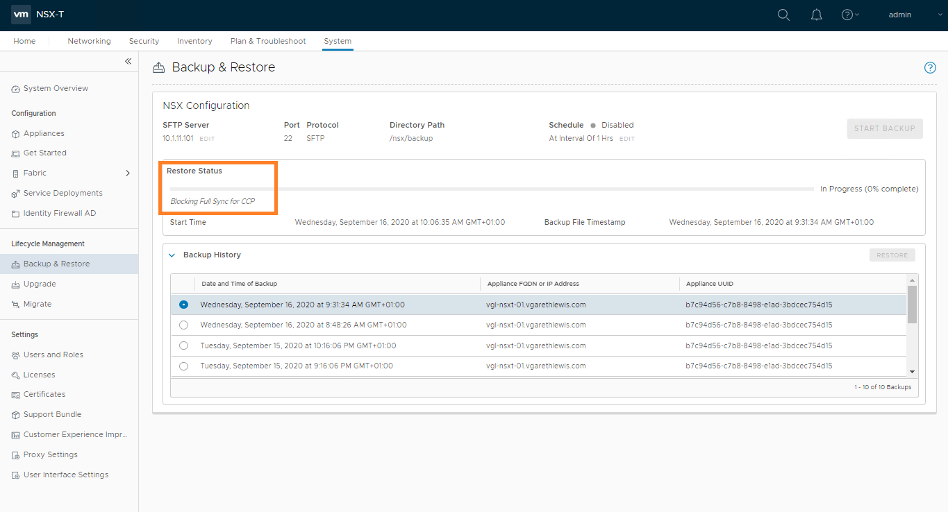
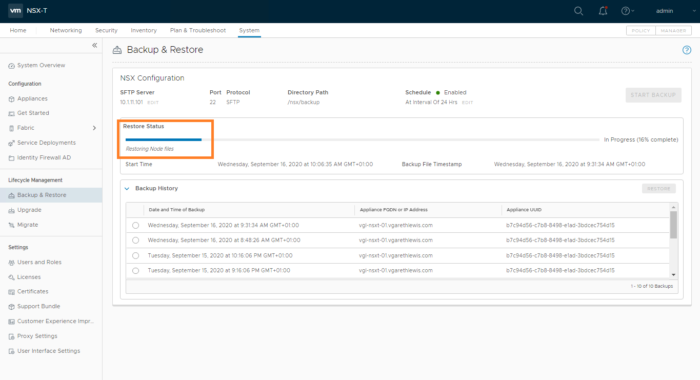
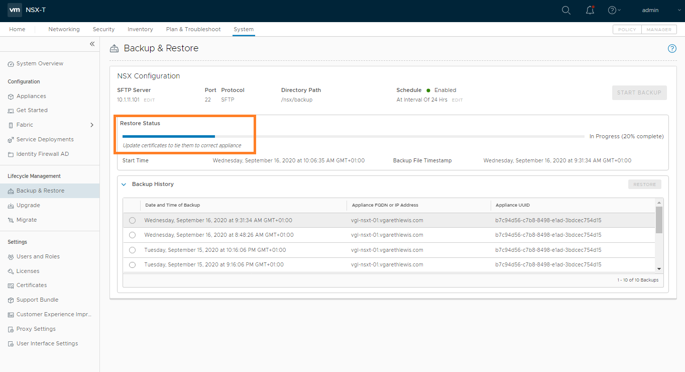
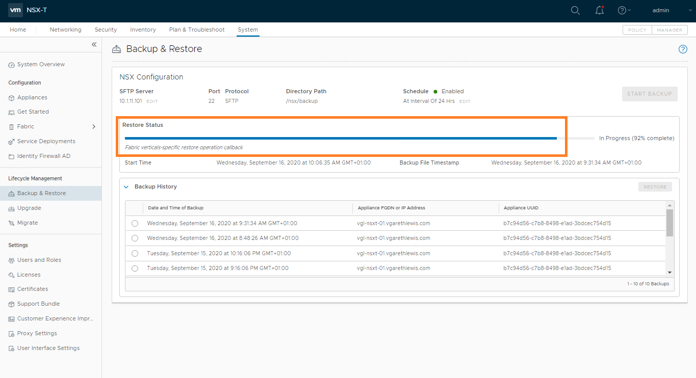
During the restore process, you will be prompted to deploy additional NSX Manager appliances. In my lab environment this is not the case as I only have one NSX Manager appliance.
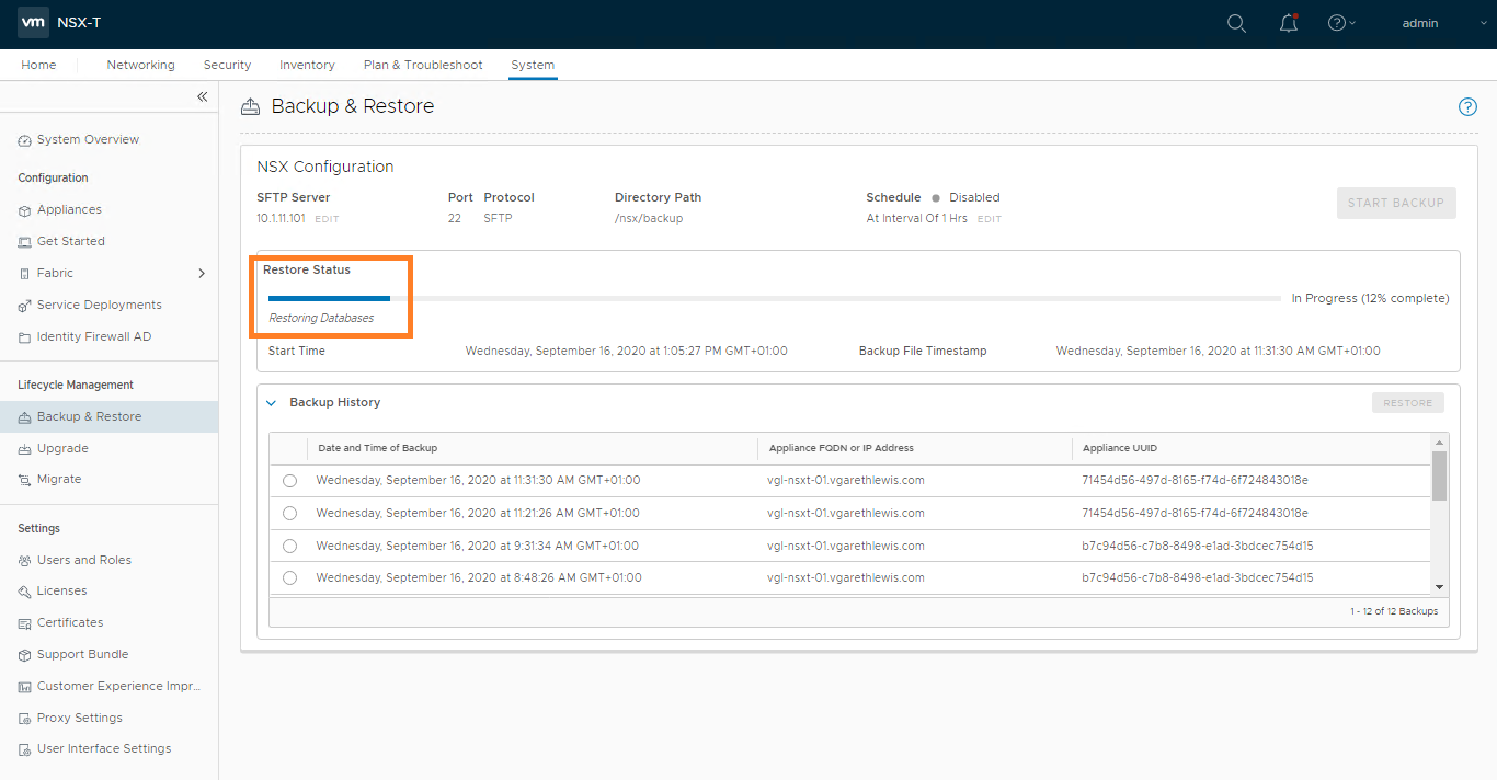
Once the restore operation completes, you will be presented with the timestamp of the backup file, as well as the start and end time of the restore operation.

5. Validate Transport Node Connectivity
To validate controller connectivity, simply SSH onto a host or edge transport node and, via nsxcli, run the below command:
get controllersAs you can see from the below screenshot, I am connected to one of my host transport nodes (ESXi). After a short amount of time following the configuration restore, the host will connect to the new NSX Manager (10.1.11.100) via the FQDN, vgl-nsxt-01.vgarethlewis.com. This is dependant on your DNS TTL.

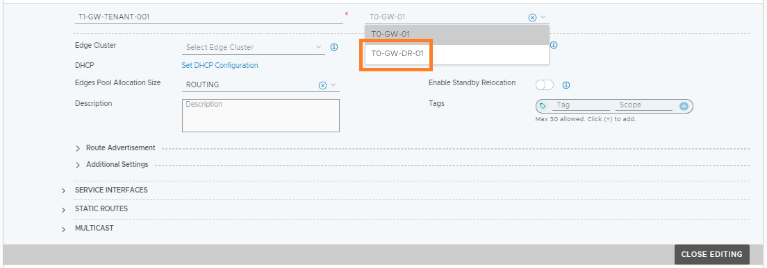
6. Site B Tier-1 to Tier-0 Connectivity and BGP Validation
Now that the transport nodes are connected to the new NSX Manager, we can switch the global Tier-1 Gateway’s uplink from the Site A Tier-0 Gateway to the Tier-0 Gateway at Site B.
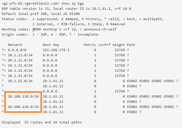
As the Tier-0 Gateway at Site B is now aware of the downstream NSX-T Overlay networks, it will advertise these to the upstream physical routers at Site B. We can confirm this by looking at the BGP configuration on one of Site B’s upstream routers.
7. Validate Site B Ingress/Egress Traffic
Finally, via a VM housed on one of the overlay networks, we test connectivity to the physical world and can see test ICMP traffic is routing to the destination via the Tier-0 Gateway at Site B.
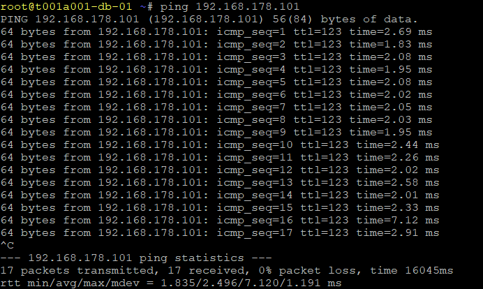
This concludes the NSX-T Failover/Restore procedure.
In the event of all issues at Site A being resolved, to failback operations to Site A, you will need to delete Site A’s legacy NSX-T Managers, deploy a new appliance, and repeat the above restore procedure. As ingress/egress traffic will be via Site B (which will hopefully be stable as you work on deploying the new NSX-T Managers to Site A), there will only be a loss of service when attaching the global Tier-1 Gateway to the Tier-0 Gateway in Site A and as the BGP routes are relearned. An out-of-hours piece of work for sure.
Leave a Reply