For those coming from an NSX-V background, you’ll remember how we enabled east-west traffic by deploying Distributed Logical Routers (DLR). This has changed ever so slightly in NSX-T, with earlier versions using Tier-1 Logical Routers, and in 2.4, Tier-1 Gateways.
To give an overview, Tier-1 Gateways (or more specifically, the Distributed Router component of the Tier-1 Gateway):
- Provide basic packet-forwarding functionality
- Are able to span all transport nodes (hypervisors and edge transport nodes)
- Run as a kernel in the ESXi hypervisor or as an OVS file in the KVM
- Provide distributed east-west routing functionality
- Provide local routing on the hypervisors.
On and off ramp gateway services (such as north-south routing) are handled by Tier-0 Gateways, and these will be covered in detail in the next article.
This article assumes you have successfully deployed your NSX Manager appliance(s), connected your vCenter Server as a Compute Manager, created your Transport Zones and Host Transport Node Uplink Profiles, and have successfully added your Host Transport Nodes.
The Scenario
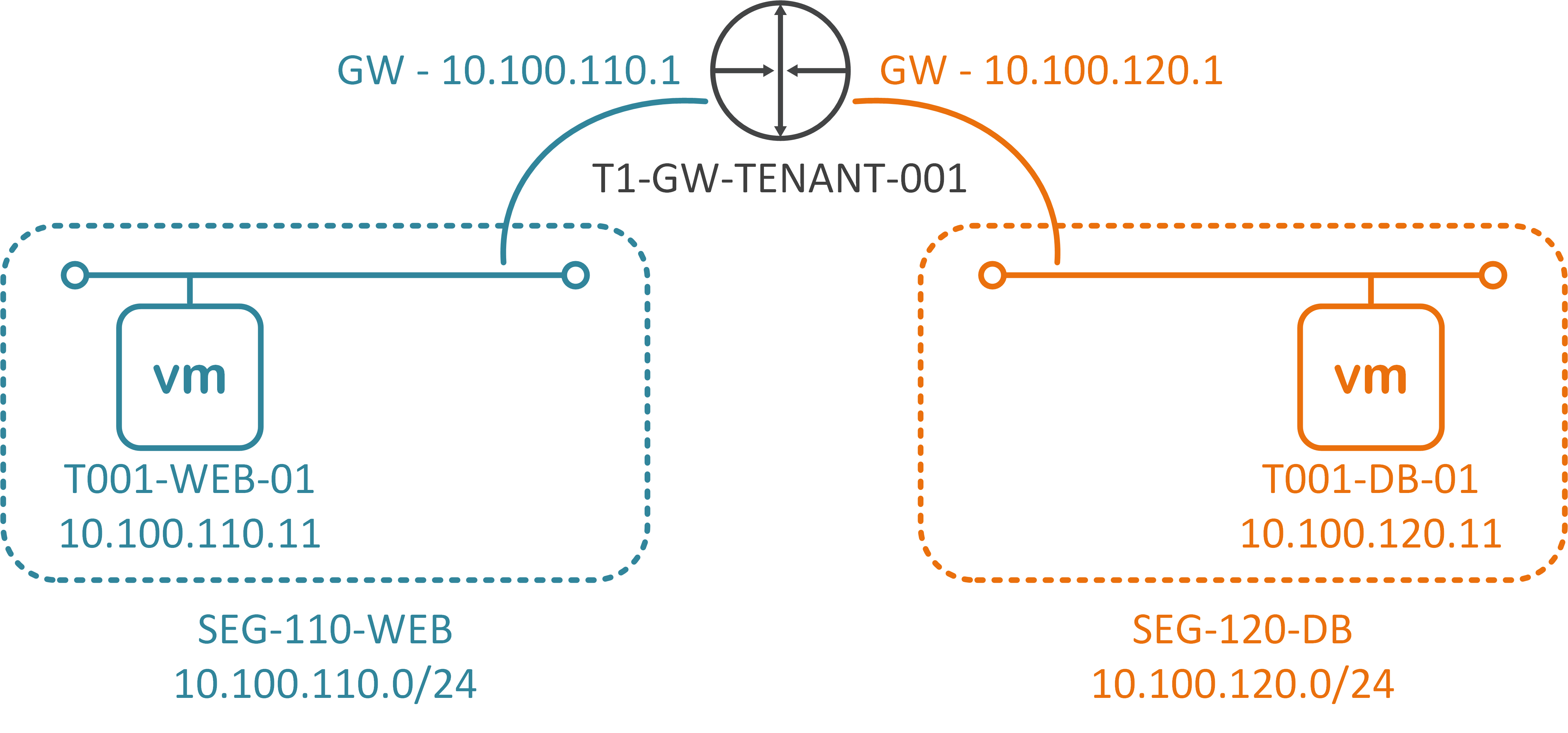
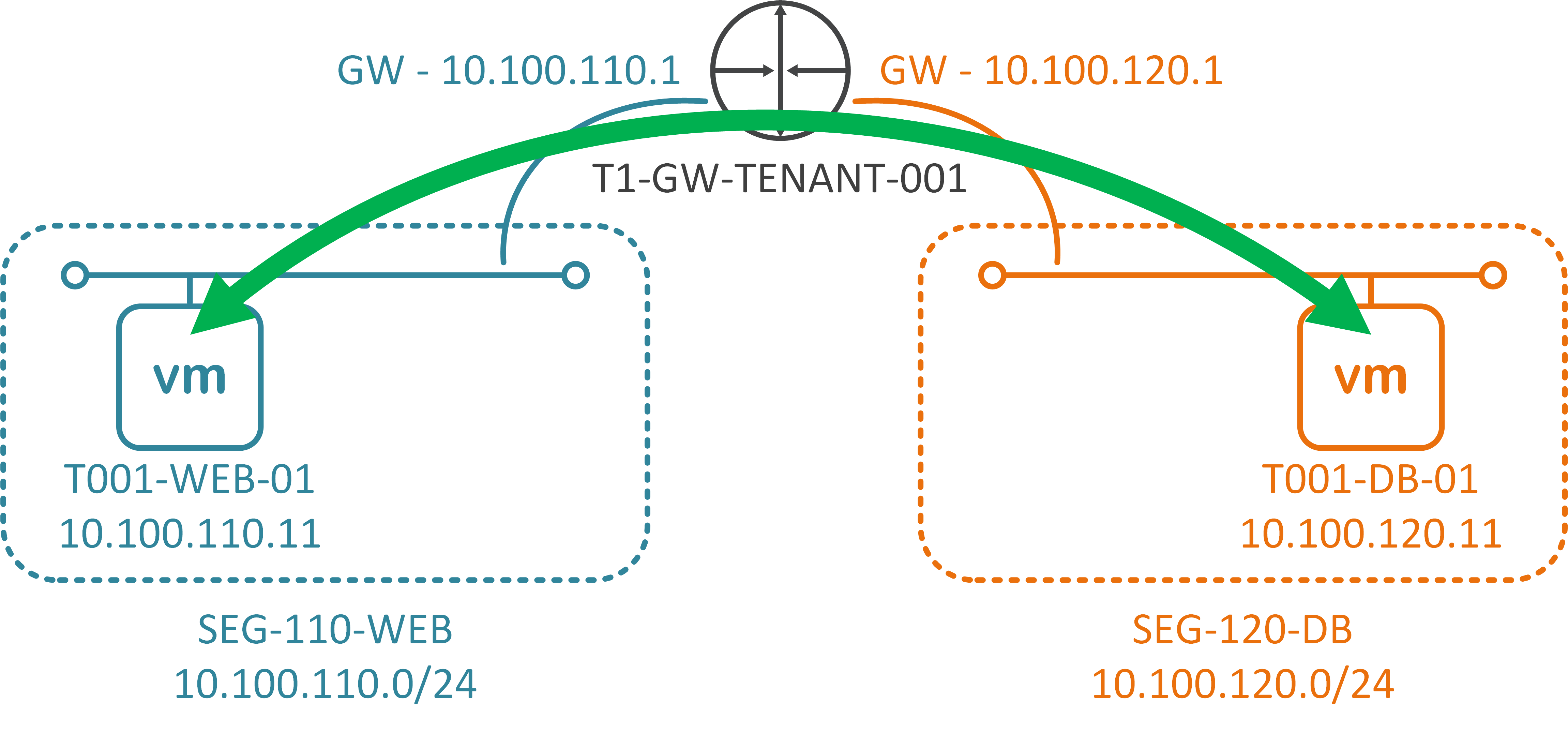
A customer/tenant needs to host a single two-tier application. This two-tier application is made up of two virtual machines. Each VM will be hosted on it’s own subnet/network segment, and each will connect to an upstream Tier-1 Gateway (T1-GW-TENANT-001) for east-west routing.
Further clarity regarding the VMs can be seen via the below table:
| VM Name | Role | IP Address | Gateway/Tier-1 Gateway Interface |
| T001-WEB-001 | Web Server | 10.100.110.11/24 | 10.100.110.1 |
| T001-DB-001 | Database Server | 10.100.120.11/24 | 10.100.120.1 |
To create the above topology (and to enable east-west connectivity between the two VMs) we will step through the below process:
- Create a Tier-1 Gateway
- Create two Segments (Web-Tier and Database-Tier) and attach to the Tier-1 Gateway
- Add VMs to the appropriate Segment and amend each of the VM’s IP configuration
- Test connectivity between VMs.
Prerequisites
Before we jump into creating our Tier-1 Gateway and Segments, let’s take a look at the prerequisites.
1. I’ve already added my vCenter Server as a Compute Manager, the Connection Status for which is a health ‘Up’.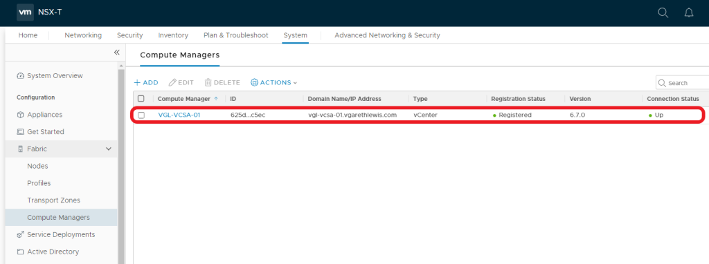
2. I’ve also created two Transport Zones (one for Overlay traffic and one for VLAN-backed traffic). Both of these Transport Zones have been assigned to an N-VDS (NVDS-PRODUCTION), the status for each is again a health ‘Up’.
3. Lastly, I’ve added my compute vSphere Cluster and have assigned the cluster a Transport Node Profile.The latter is completely optional, although is recommended to ensure configuration consistency across all vSphere Hosts (ESXi). The NSX-T Tunnel End Point (TEP) on each of my hosts has been assigned an IP address from an NSX-T IP Address Pool, required in order to encapsulate and pass this traffic between hosts via the GENEVE protocol.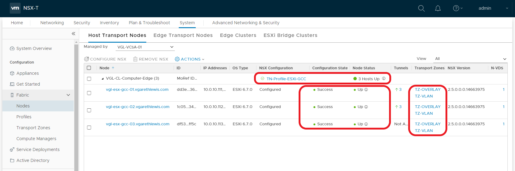
1. Create a Tier-1 Gateway
1.1 Navigate to Networking > Tier-1 Gateways and click Add Tier-1 Gateway.
1.2 Give the new Tier-1 Gateway a Name and click Save.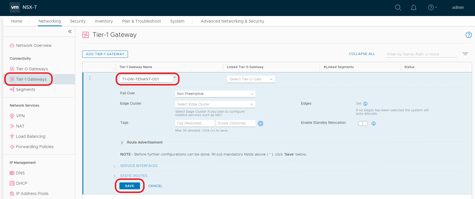
1.3 When prompted to ‘…continue configuring this Tier-1 Gateway?’, click NO.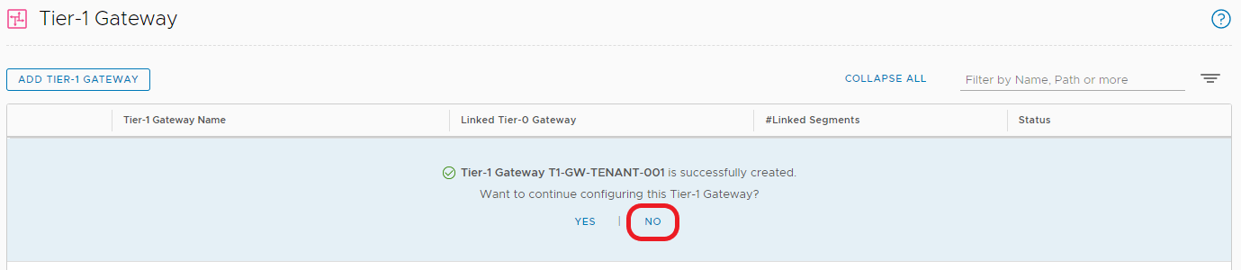
2. Create Segments
Next we will create two logical networks – i.e. Segments. One will be utilised by our Web Tier (SEG-110-WEB), and will house our Web Server VM (T001-WEB-01), and the second Segment will be utilised by our Database Tier (SEG-120-DB), and will house our Database Server VM (T001-DB-01).
2.1 Navigate to Networking > Segments and click Add Segment.
2.2. Give the new Segment a Name (1), connect the Segment to the recently created Tier-1 Gateway from the Connected Gateway & Type drop-down menu (2), select the Overlay Transport Zone (3), and click Set Subnets (4).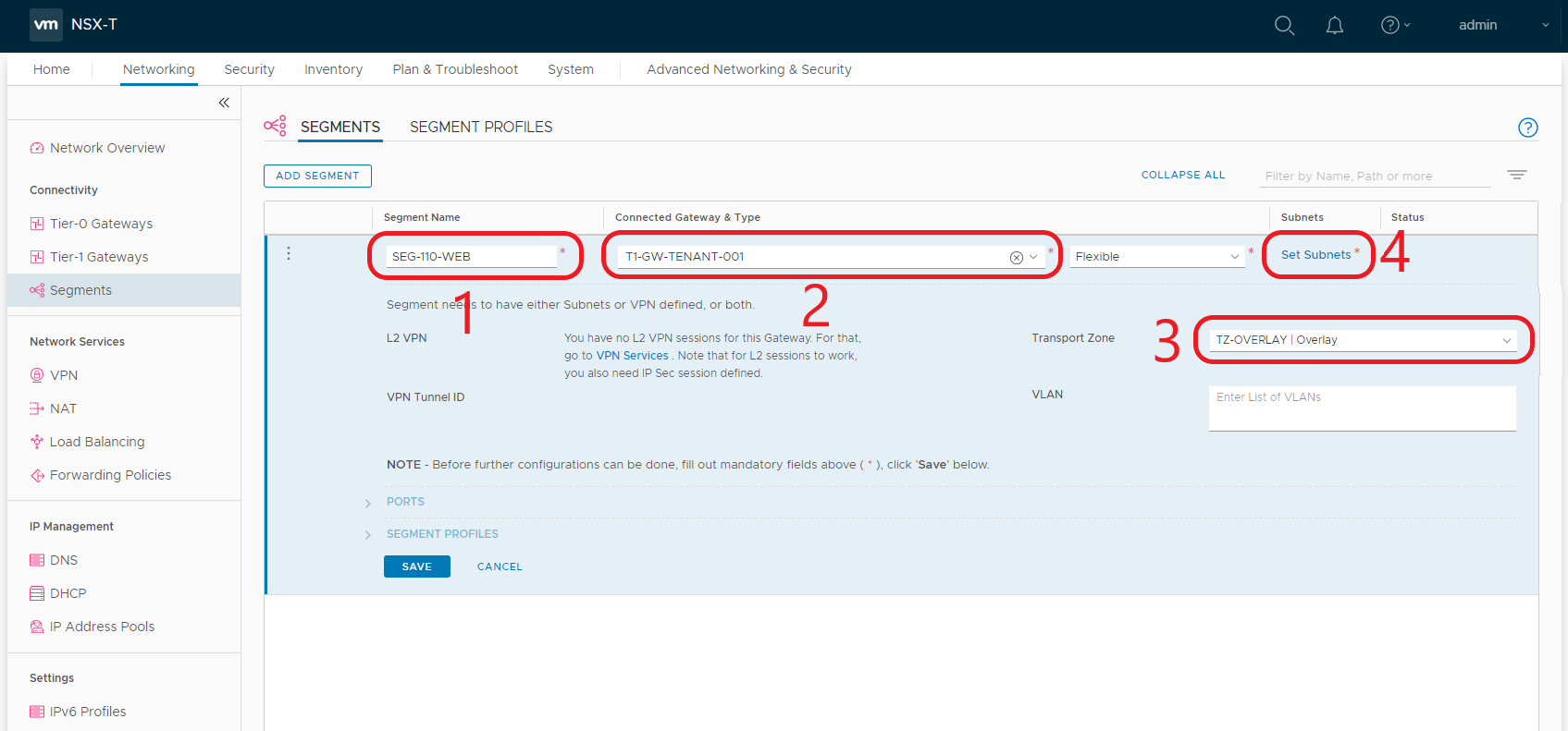
2.3 When the Set Subnets window opens, click Add Subnet.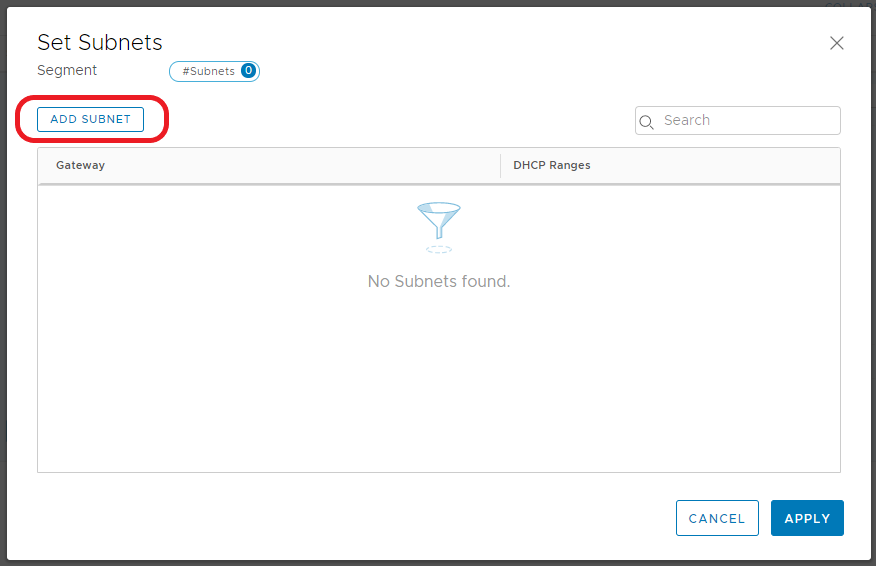
2.4 Enter the IP address in CIDR format. This will act as the Segment’s Gateway and, in turn, the default gateway for any virtual machines housed on this Segment. When ready, click Add. 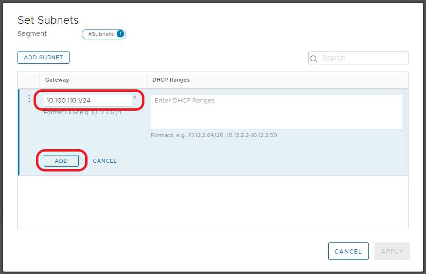
2.5 Click Apply.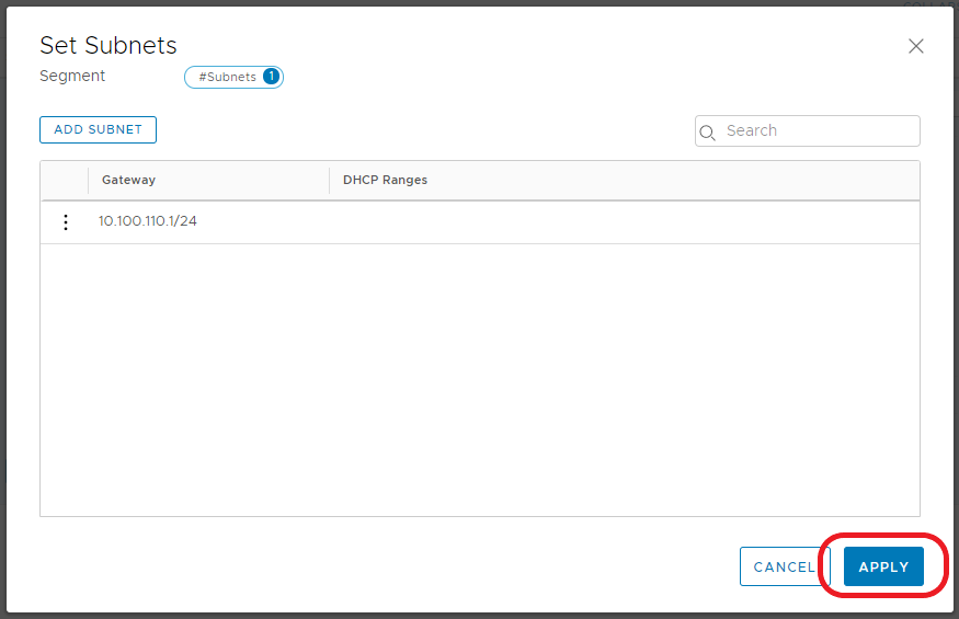
2.6 Note the Subnet count now shows ‘1’. When ready, click Save. 
2.7 When prompted to ‘…continue configuring this Segment?’, click NO. 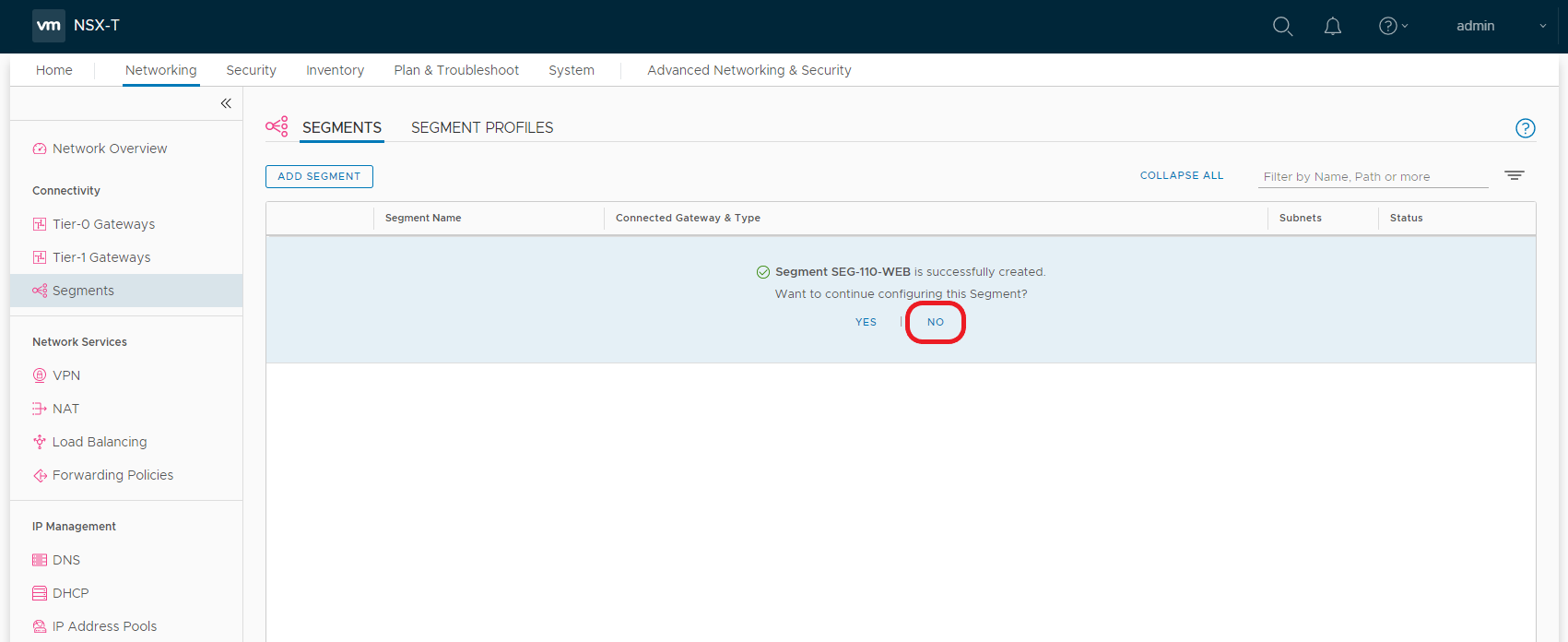
2.8 After a moment, the Segment’s status should display ‘Up’. If not, click Refresh at the bottom of the screen.
2.9 Repeat steps 2.1-2.8 to create the Database subnet/Segment (10.100.120.1/24). Once complete, you should see the two new Segments displayed as below, both of which should be connected to our Tier-1 Gateway.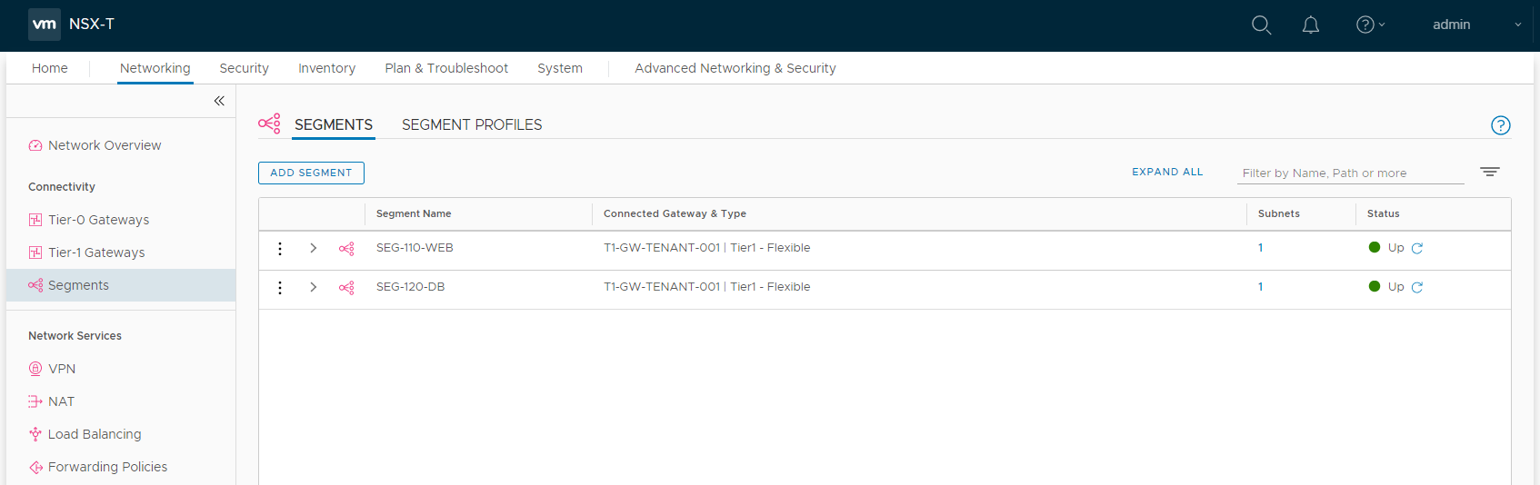
2.10 Let’s take a quick look at how these Segments are displayed via the vSphere Client. Browsing to one of our vSphere Hosts (Hosts and Clusters > Configure > Virtual Switches), we can see the new Segments have been attached to our N-VDS.
2.11 Likewise, via the Networks tab, the new Segments are displated under the vSphere Datacentre (in my case ‘SDDC-UK-CARDIFF’).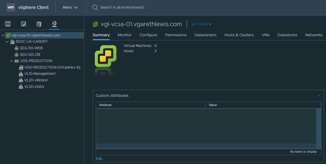
3. Add VMs to Segments
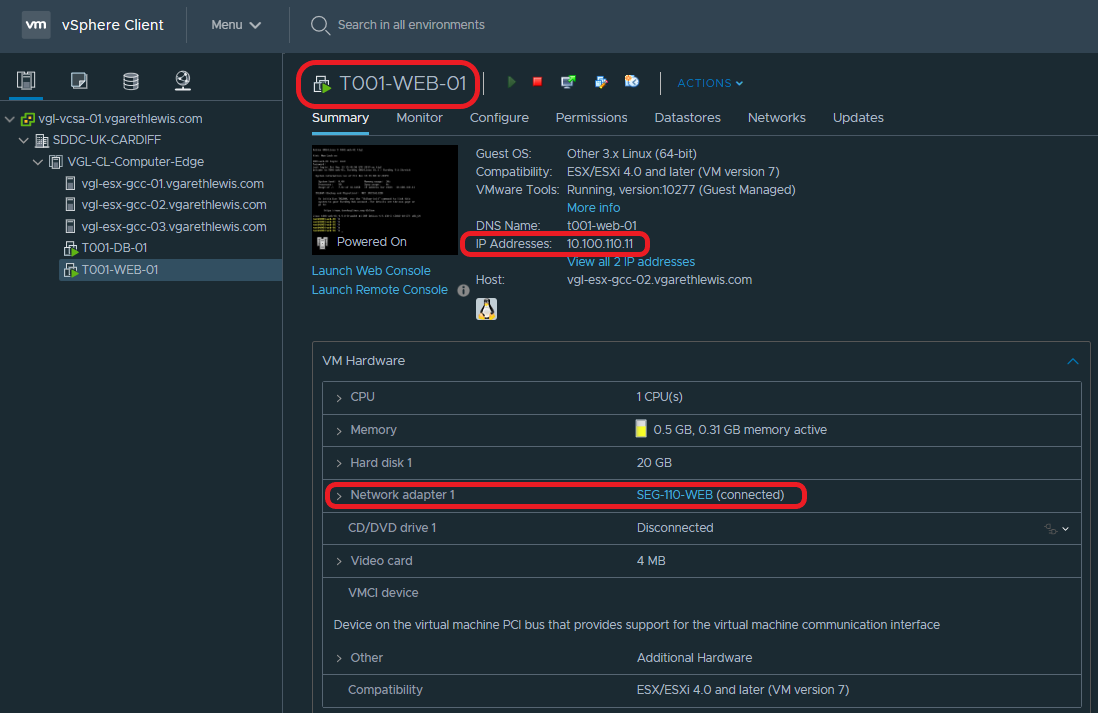
Lastly, we simply need to add a workload into our new NSX-T Segments. In the below screenshots you will note the deployment of two VMs – a Web Server (T001-WEB-01) and a Database Server (T001-DB-01). Each VM has been assigned to the appropriate NSX-T Segment, and their IP configuration amended to reflect it’s subnet and the correct default gateway (i.e. – the correct interface on the Tier-1 Gateway).
| VM Name | Role | IP Address | Gateway/Tier-1 Gateway Interface |
| T001-WEB-001 | Web Server | 10.100.110.11/24 | 10.100.110.1 |
| T001-DB-001 | Database Server | 10.100.120.11/24 | 10.100.120.1 |
Web Server – T001-WEB-01:
Database Server – T001-DB-01: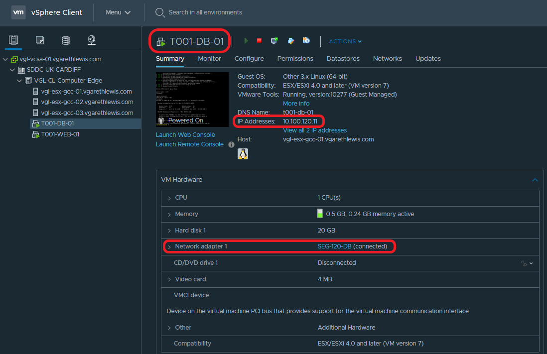
4. Test Connectivity
Each VM is now housed in a suitable network segment, and each VM has been configured to route via an interface on the upstream Tier-1 Gateway (as depicted in the below diagram).
From the below screenshots, we can see a successful ICMP test. Specifically, ICMP traffic is able to route between each of the VMs via the Tier-1 Gateway.
From T001-WEB-01 to T001-DB-01: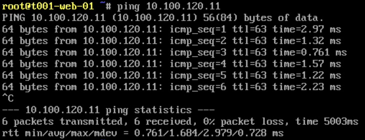
From T001-DB-01 to T001-WEB-01: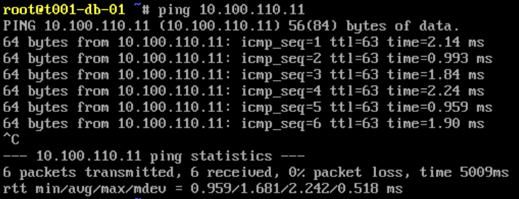
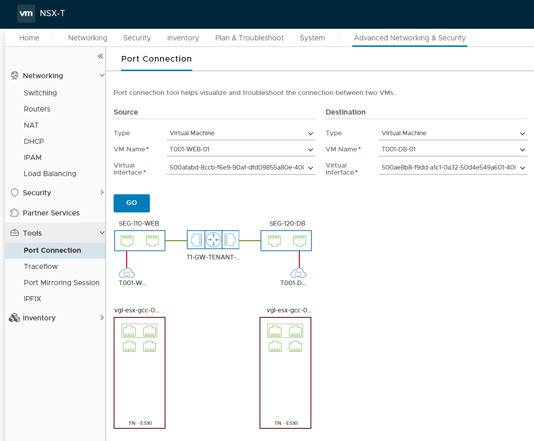
The traffic flow can also be visualised via the NSX-T UI utilising a number of tools. In the below screenshot we use the Port Connection tool.

This concludes the deployment and configuration of the Tier-1 Gateway, as well as the creation of a number of Segments which allow VMs to utilise and route traffic via the N-VDS overlay.
In Summary
In this article we covered east-west connectivity required by the components of a two-tier application. Specifically, we deployed a Tier-1 Gateway, two logical networks via NSX-T Segments, and two VMs which utilise the new Segments. Traffic between the two VMs is successful by traversing the Tier-1 Gateway, however, neither VM is able to route to the upstream physical network. For this we will require a Tier-0 Gateway.
In the next article we will enable north-south routing (from physical to virtual) by deploying and configuring a Tier-0 Gateway and all it’s prerequisite components. We will also look at a number of logical routing use cases, and the ability to separate provider and multi-tenant environments..
Excellent One. Thank you.
Excellent presentation.
Nice explanation
good explanation. Thank you.