VMware NSX Data Center for vSphere (NSX-V) has been able to leverage dynamic routing via Open Shortest Path First (OSPF) and Border Gateway Protocol (BGP) for some time and, in this article, I detail the process of configuring OSPF on both an Edge Services Gateway (ESG) and a downstream Distributed Logical Router (DLR).
OSPF, a Link State Protocol and member of the Interior Gateway Protocol (IGP) family (which also includes Routing Information Protocol (RIP), Intermediate System to Intermediate System (IS-IS), and Enhanced Internal Gateway Routing Protocol (EIGRP)), enables all participating routers to dynamically exchange network topology information to calculate the best shortest path (cost) of a route’s destination.
When a change of network topology is detected by one router (maybe a new subnet/network segment has been added to a router, or even a new router itself is added to the topology), the change is automatically advertised to all routers participating in the OSPF ‘routing area’; think neighbours (routers) in a neighbourhood (routing area). The participating routers then update their Link-State Databases (LSDBs) with the new network topology and adjust their routing tables accordingly.
Please note, this article focuses on VMware NSX Data Center for vSphere (NSX-V). It does not cover OSPF on NSX-T. Furthermore, I do not cover the creation or configuration of either Edge Services Gateway or Distributed Logical Router. For more information on these areas, simply visit the below VMware Docs:
Environment Topology
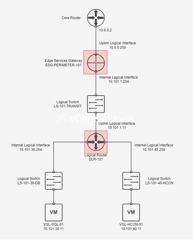
In this article we have a simple network topology (see below) comprising a perimeter ESG (essentially an Area Border Router (ABR) connected to my upstream physical network), a downstream DLR (a neighbouring ABR), two interior network segments represented by two NSX Logical Switches (LS-101-30-DB (10.101.30.0/24) and LS-101-40-HCON (10.101.40.0/24)), and two virtual machines (VGL-SQL-01 (10.101.30.11) and VGL-HCON-01 (10.101.40.11)).
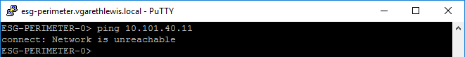
Currently, neither ESG or DLR have OSPF enabled, nor have any static routes been configured. In this scenario, routing from our ESG to either of the downstream VMs fails (evidenced by the below ICMP request). This is to be expected, as the ESG (unaware of the downstream networks) will attempt to route the traffic via its upstream gateway (i.e. – my physical network).
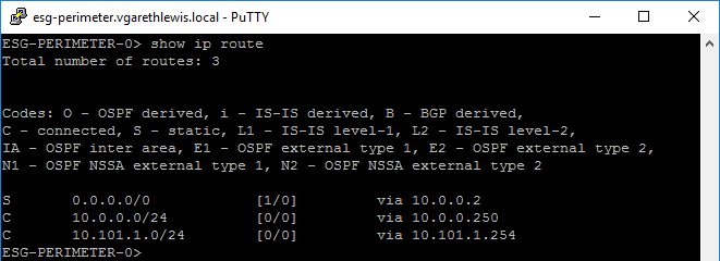
As the DLR is not currently advertising its networks to the upstream ESG, the ESG has no idea that the downstream networks even exist, let alone how to route traffic there. We can confirm this by connecting to the ESG via SSH and by running the command show ip route. From the below screenshot, we confirm that the ESG is unaware of the network segments 10.101.30.0/24 or 10.101.40.0/24. Again, this is to be expected.
Hello OSPF…
In this article we will configure the ESG and DLR to peer with each other via a Routing Area (aka, Area Definition or Area ID). Once configured, the DLR will be able to advertise its routing information with its new neighbour, the ESG. Consequently, the ESG will be able to see the previously unknown networks and will update its LSDB and routing table. Traffic will then be able to route via the correct IP address, the DLR’s Uplink Logical Interface (10.101.1.11).
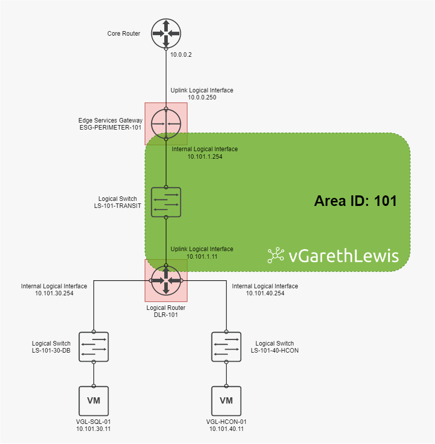
To implement the above OSPF design we will peer the ESG and DLR by assigning a Router ID to both devices, enabling OSPF, creating the Area Definition and mapping it to the appropriate Logical Interface, and by enabling the distribution of routes between each of the peered routers.
Edge Services Gateway Configuration
1. Browse to Networking and Security > NSX Edges and edit your Edge Services Gateway.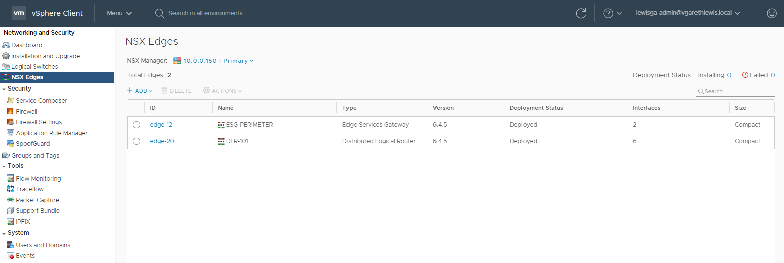
2. Browse to the Routing > Global Configuration and edit the Dynamic Routing Configuration.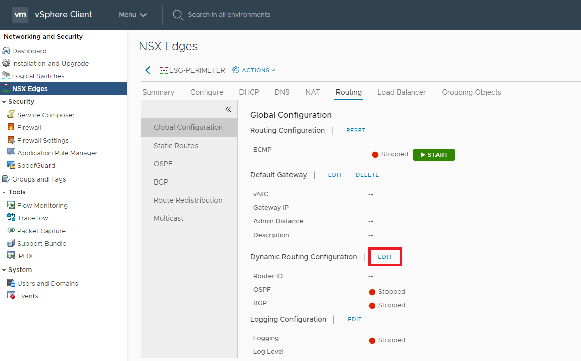
3. Select the ESG’s uplink Logical Interface and click Save.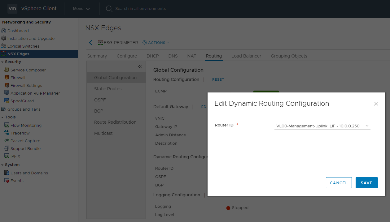
4. Confirm the Router ID has been set and, when ready, click Publish.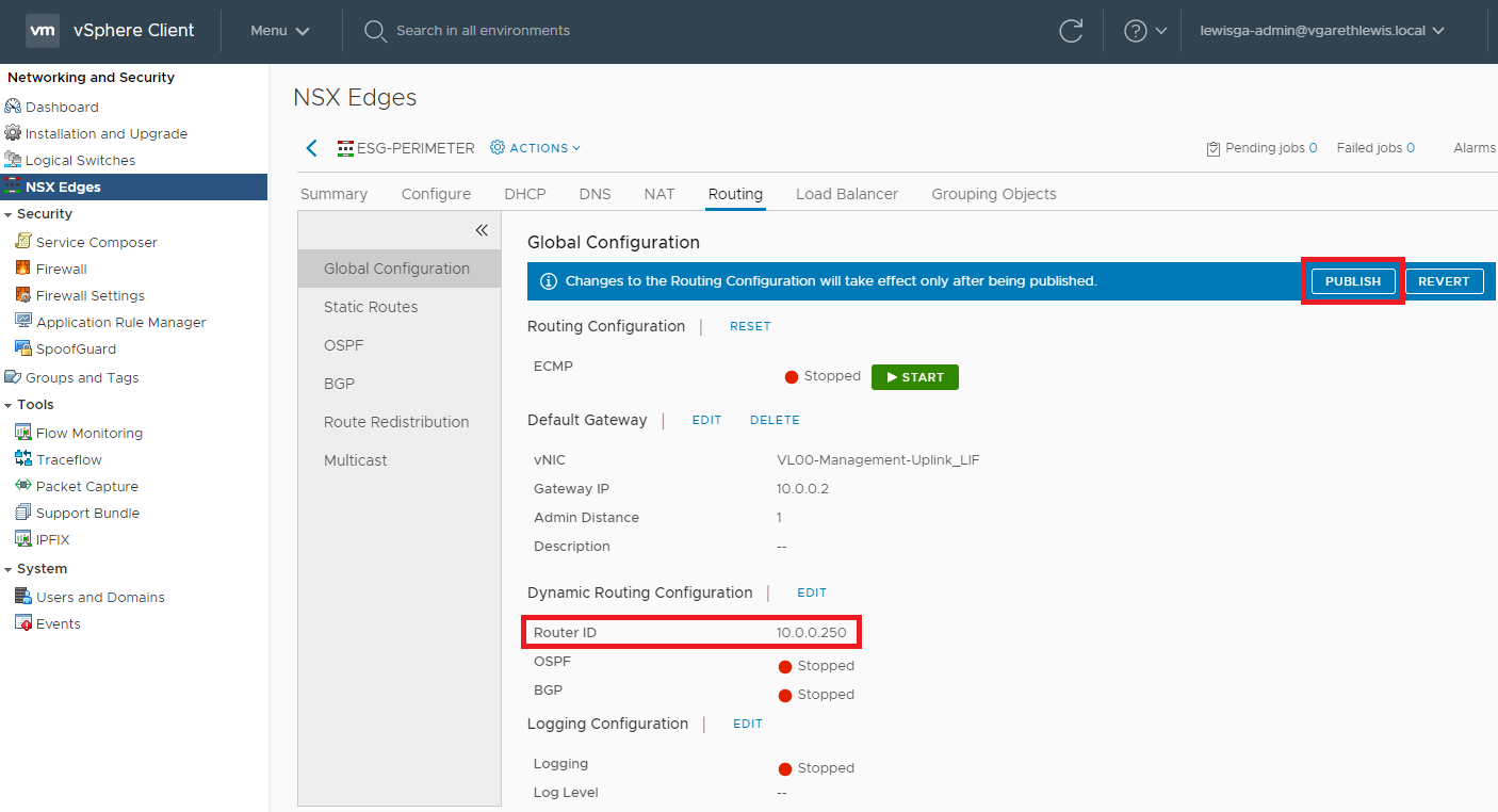
5. Confirm the publish action has completed successfully.
6. Browse to Routing > OSPF. Enable OSPF by editing the Configuration, add an Area Definition and add an Area to Interface Mapping.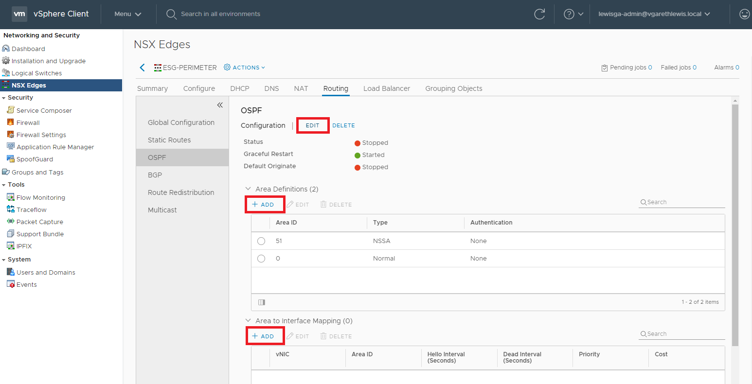
7. After clicking Edit configuration, Enable the Status and click Save.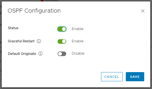
8. Create a new Area Definition by assigning an Area ID (in our case 101), and click Save.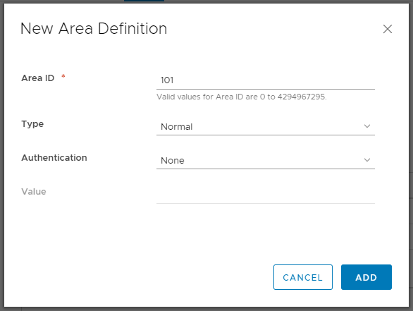
9. Map the newly created Area ID to a suitable vNIC. Referring back to our OSPF design, we will map the Area ID to the ESG’s Internal Logical Interface (10.101.1.254). Once done, click Add.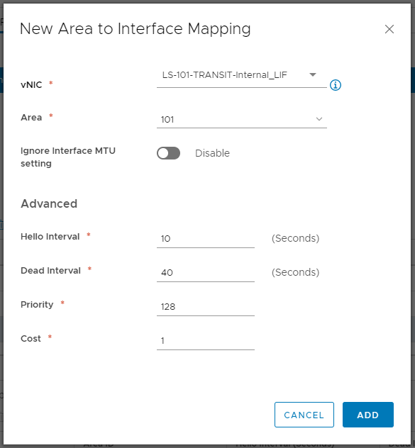
10. As usual, the change will require a Publish action. When ready, click Publish.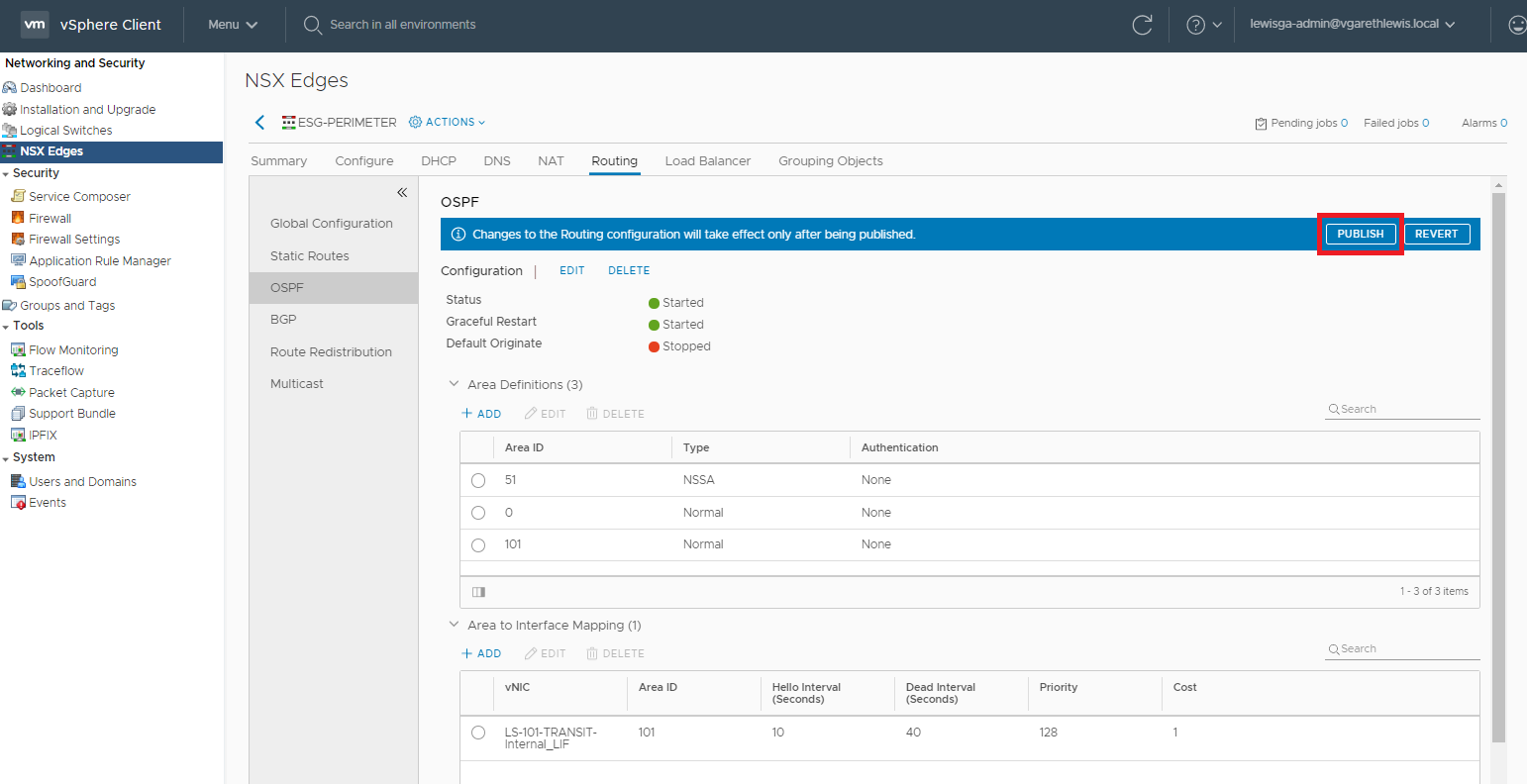
11. Confirm the publish action has completed successfully.
12. Browse to Routing > Route Redistribution. Enable OSPF Router Redistribution and add a new Router Distribution Table criteria. 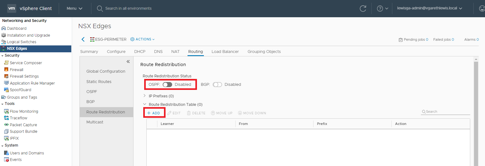
13. The Redistribution Criteria can be seen below. Set the Learner Protocol to OSPF, and configure Allow Learning From based on your requirements. In my case I have no Static Routes configured, so I only need to select Connected.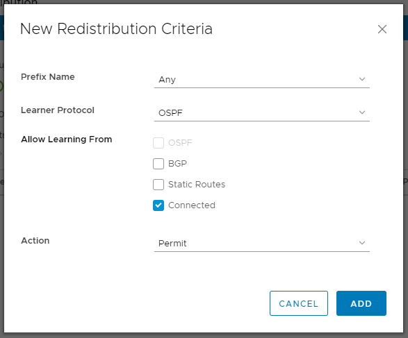
14. As usual, the change will require a Publish action. When ready, click Publish.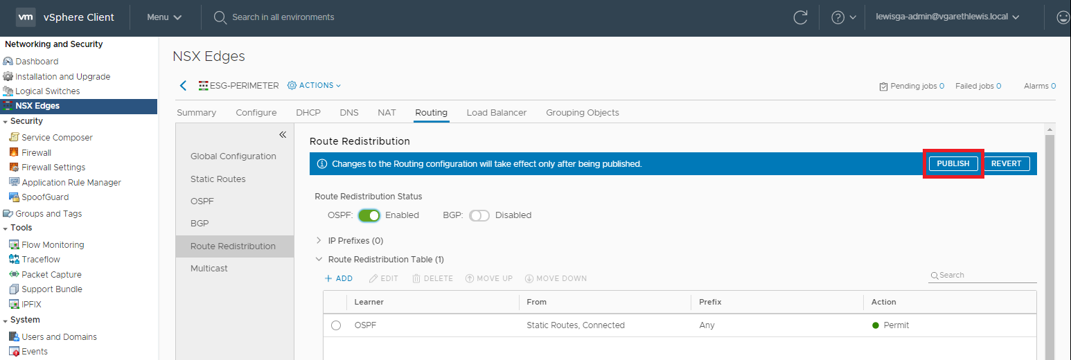
15. Confirm the publish action has completed successfully.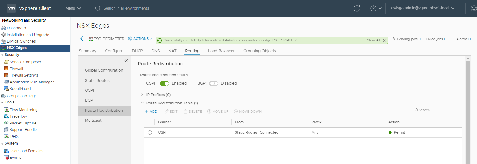
This concludes the configuration of the Edge Services Gateway.
Distributed Logical Router Configuration
1. Browse to Networking and Security > NSX Edges and edit your Distributed Logical Router.
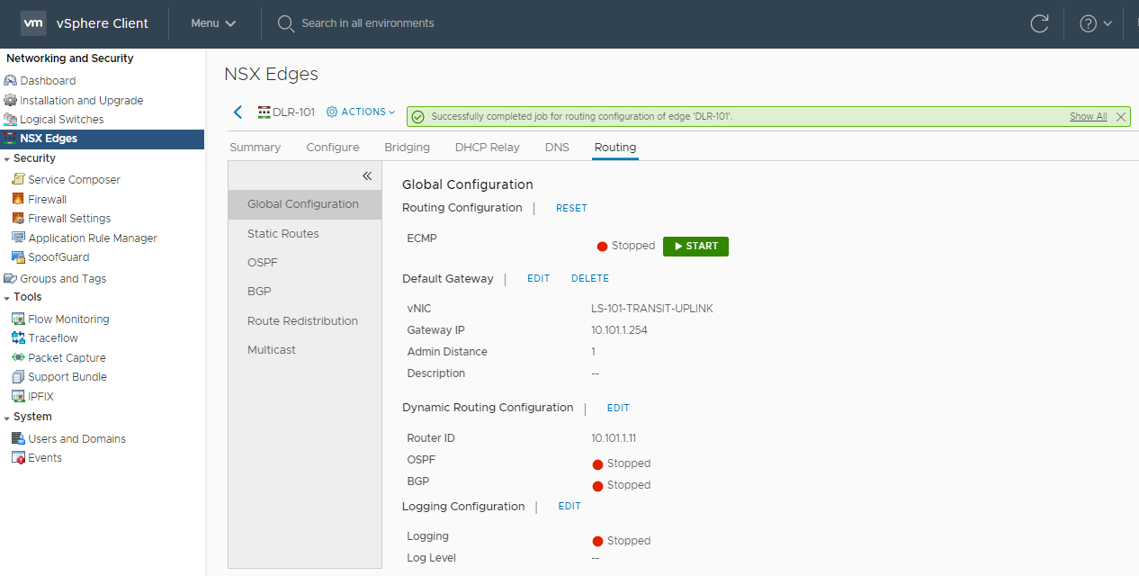
2. Browse to Routing > Global Configuration and edit the Dynamic Routing Configuration.
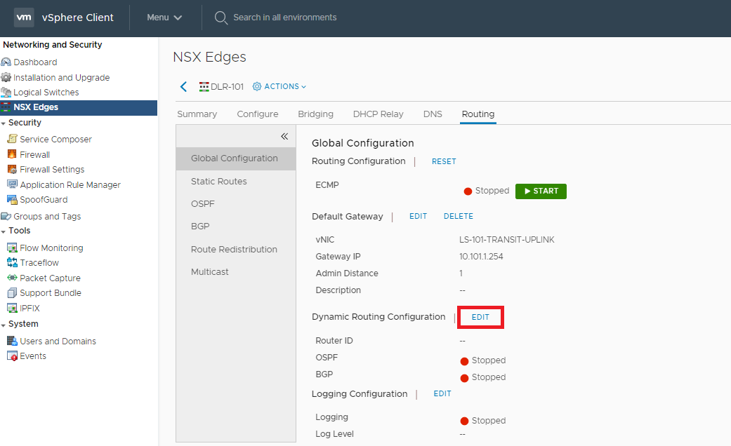
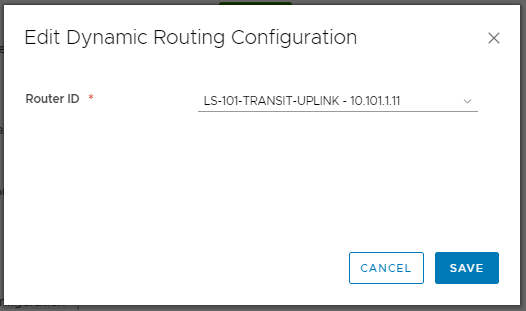
3. Select the DLR’s uplink Logical Interface and click Save.
4. As usual, the change will require a Publish action. When ready, click Publish.
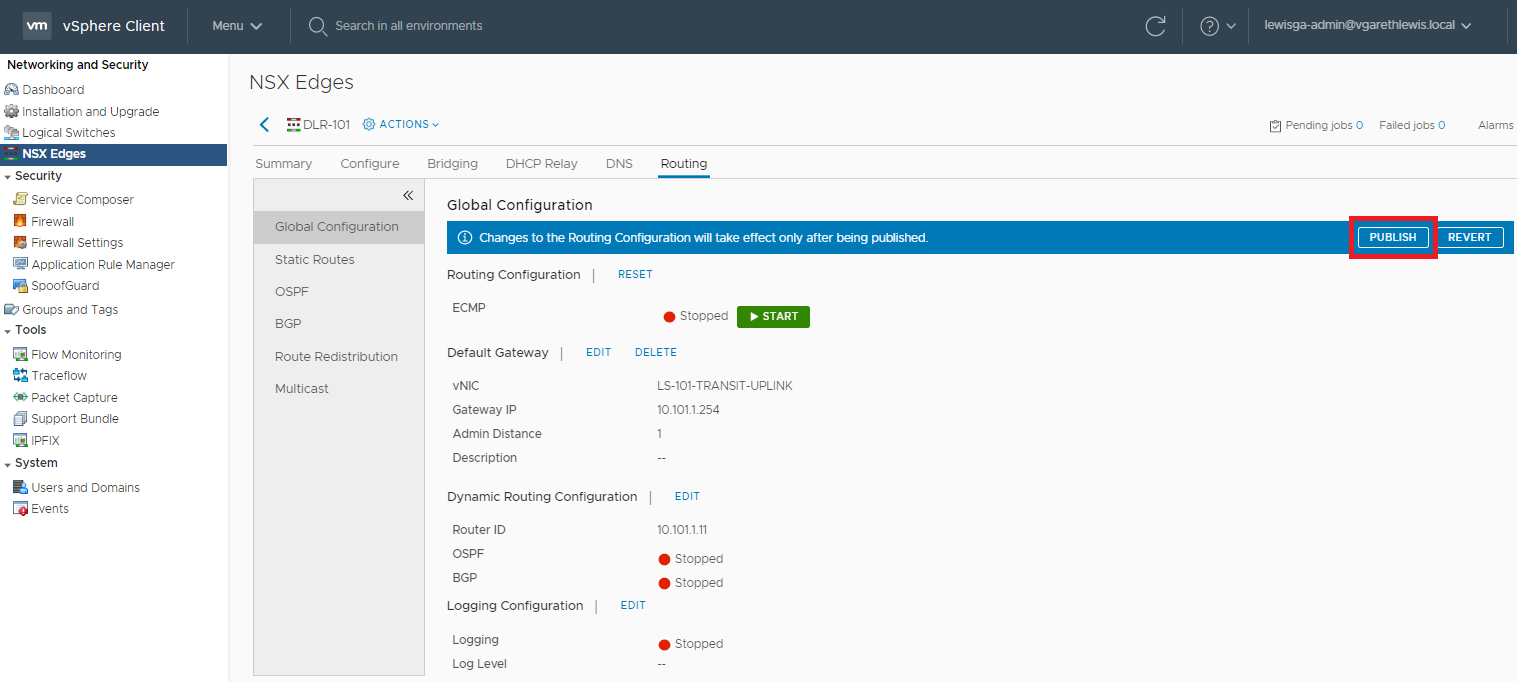
5. Confirm the publish action has completed successfully.
6. Browse to Routing > OSPF. Enable OSPF by editing the Configuration, add an Area Definition and add an Area to Interface Mapping.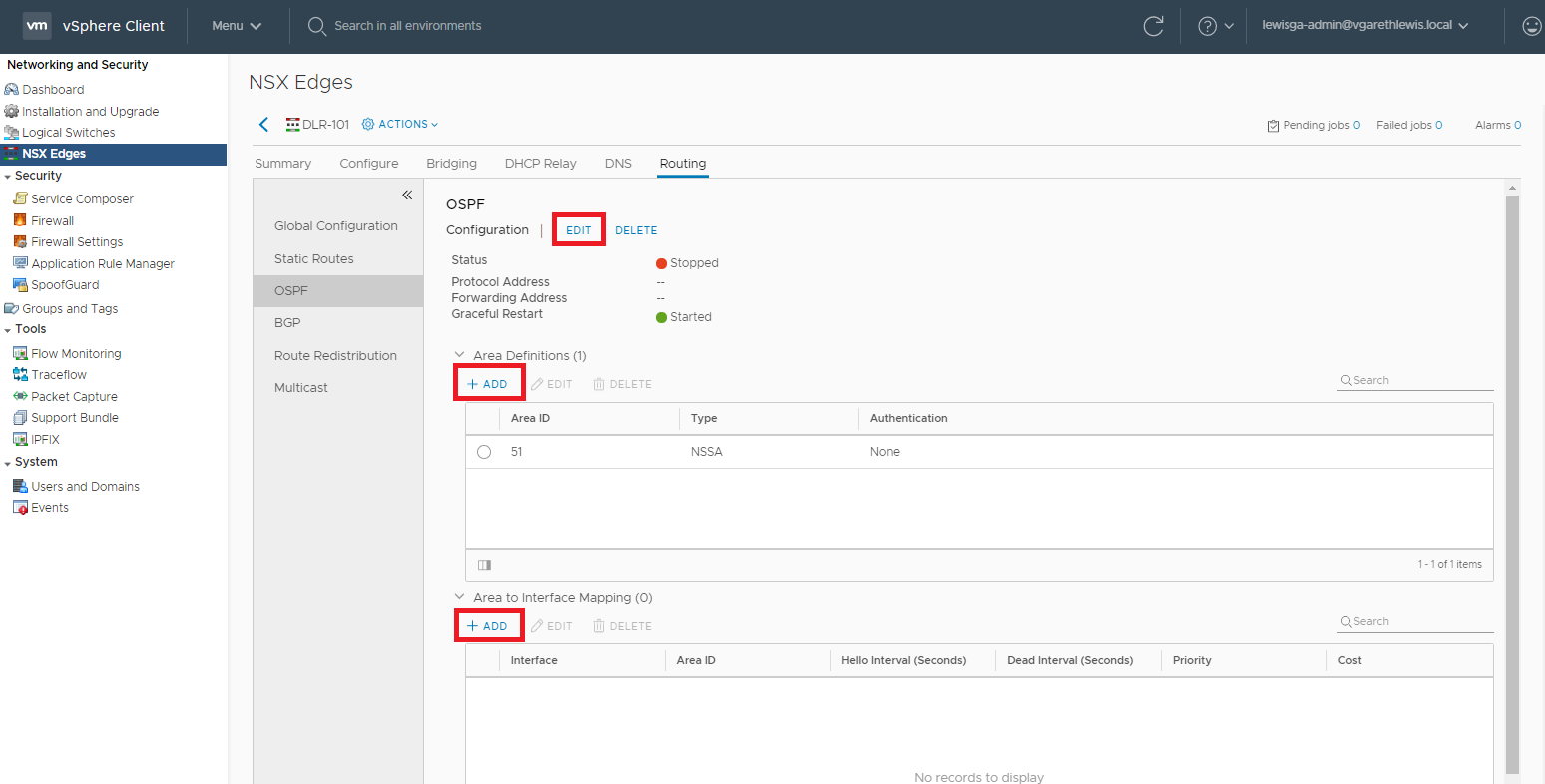
7. Via the OSPF Configuration dialogue box, set the Interface to the Uplink Logical Interface, Enable the Status slider, and assign a Protocol Address.
Note, I see a lot of questions relating to protocol and forwarding address. Specifically, what’s the difference? VMware classifies these as:
- Forwarding Address – ‘…an IP address that is to be used by the router datapath module in the hosts to forward datapath packets.‘ This is the Router ID.
- Protocol Address – ‘The protocol address is used by the protocol to form adjacencies with the peers.‘ This is essentially a proxy address.
Once complete, click Save.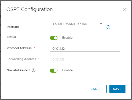
8. Create a new Area Definition by assigning an Area ID (in our case 101), and click Save.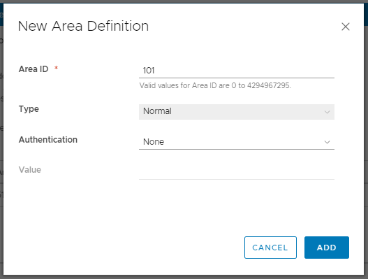
9. Map the newly created Area ID to a suitable vNIC. Referring back to our OSPF design, we will map the Area ID to the DLR’s Uplink Logical Interface (10.101.1.11). Once done, click Add.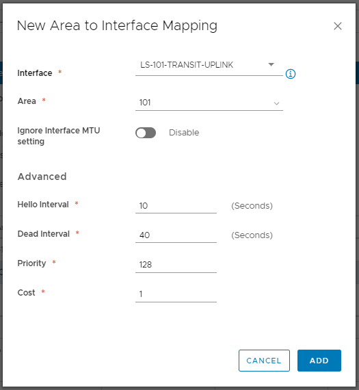
10. As usual, the change will require a Publish action. When ready, click Publish.
11. Confirm the publish action has completed successfully.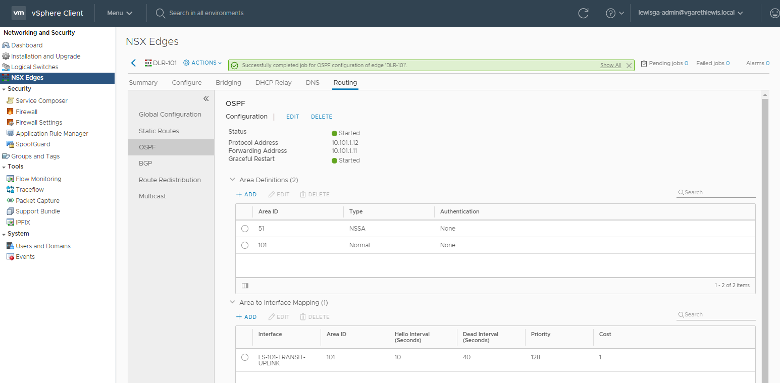
12. Browse to Routing > Route Redistribution. Enable OSPF Router Redistribution and add a new Router Distribution Table criteria.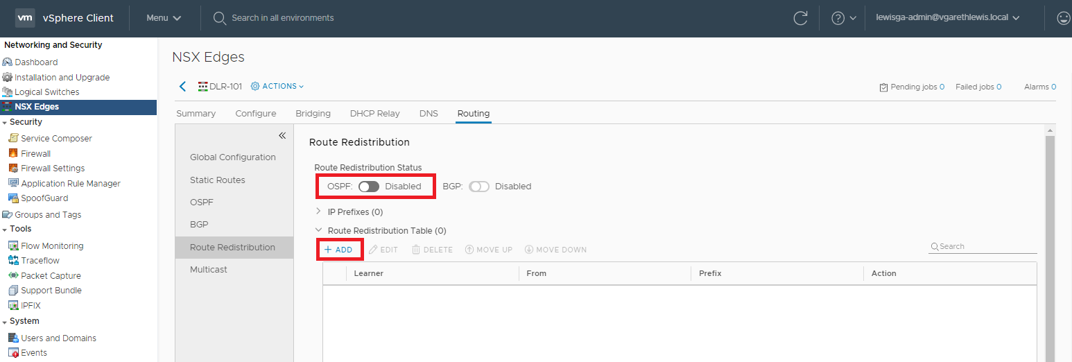
13. The Redistribution Criteria can be seen below. Set the Learner Protocol to OSPF, and configure Allow Learning From based on your requirements. Again, in my case I have no Static Routes configured, so I only need to select Connected.
14. As usual, the change will require a Publish action. When ready, click Publish.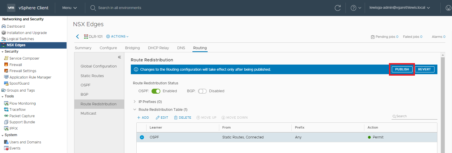
15. Confirm the publish action has completed successfully.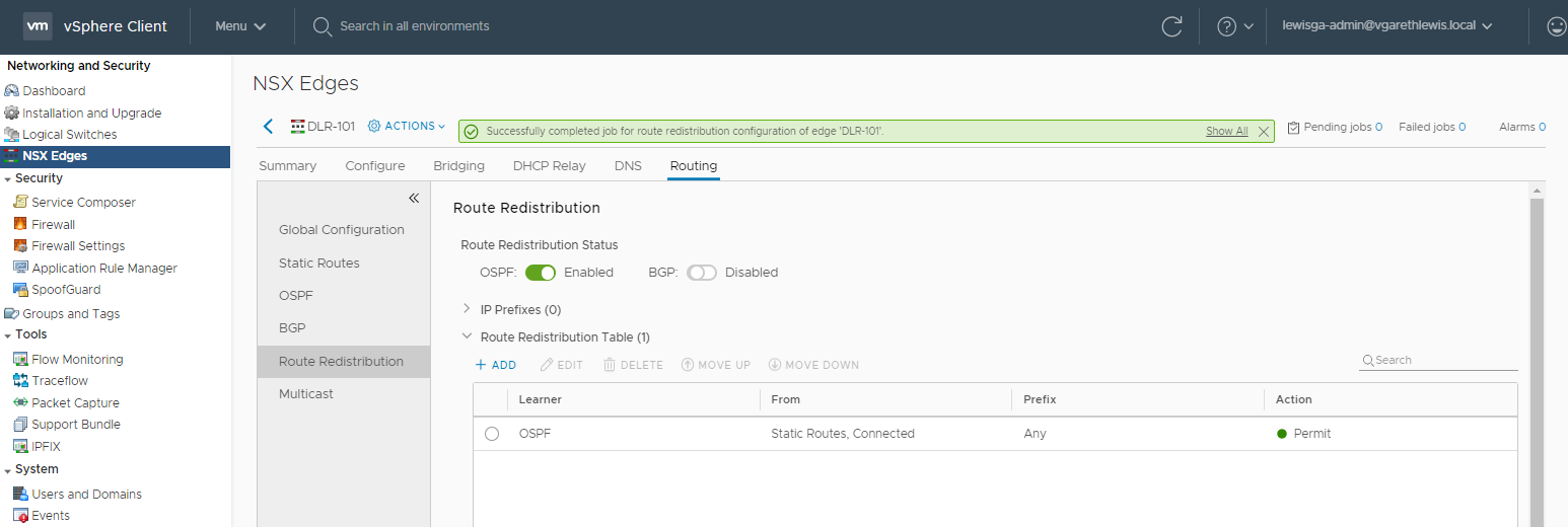
This concludes the configuration of the Distributed Logical Router.
OSPF Testing
With OSPF now configured on both the ESG and DLR, let’s revisit our earlier issue whereby the ESG was unable to route ICMP traffic to a downstream virtual machine via our DLR.
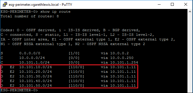
Connecting to our ESG via SSH, we run the show ip route command again. We can see that the downstream DLR has now been successful in advertising its networks to the upstream ESG. Consequently, the ESG has updated its LSDB and routing tables and now knows to route traffic to both downstream subnets via the DLR’s Uplink Logical Interface (10.101.1.11).
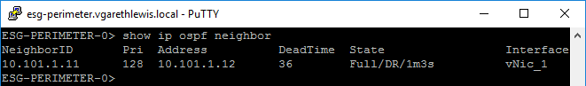
We can also confirm the OSPF neighbour peered with the ESG by running show ip ospf neighbor. As you can see via the below screenshot, you’ll note the OSPF neighbour is identified as our DLR via it’s NeighborID (Forwarding Address/RouterID) on 10.101.1.11 and it’s Address (Protocol Address/Proxy) on 10.101.1.12.
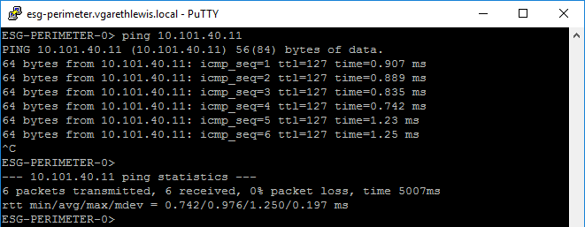
Finally, re-running the same ICMP test as earlier is now successful thanks to the updated routing information.
This concludes the configuration of OSPF within an NSX-V environment, however, if you have any queries please feel free to reach out.
Nice article. I think its good to have OSPF NSSA area between DLR & ESG. This way, each DLR doesn’t see the E2 routes advertised from other DLR’s improving tenant isolation from a control plane perspective.
Great comment Harikrishnan, and I totally agree when implementing within a tenant architecture. I remember enjoying your blog posts on this from earlier in the year.